Stress testing of PV cell and energy storage
Evaluate light energy harvesting system for your embedded device
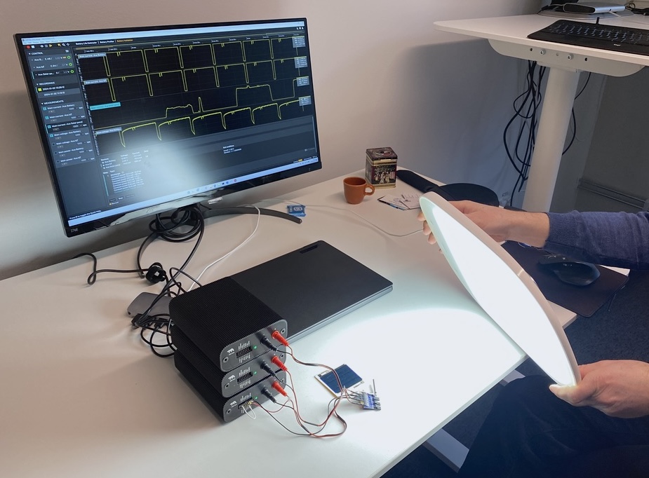
Ensuring the self-sustainability of a photovoltaic (PV) system is crucial for long-term operation of electronics. Developers need precise data on the energy generated by the harvester, stored in the energy storage, and consumed by the device during active, communication, and sleep states.
Three (3) Otii Aces are needed for this use case. Two (2) Otii Aces each are used in-line with the PV cell and energy storage to evaluate their performances. One Otii Ace is used as a load, aka the IoT device. Otii Ace as load gives the flexibility of testing the photovoltaic system for different device use cases for example communication protocols, duty cycles and more. You customize the Otii Ace behaviour based on the power profile of your embedded device and use cases.
Regardless of if you are evaluating photovoltaics for indoor electronics or IoT solar panels, this the set-up to assure the longevity of the system.
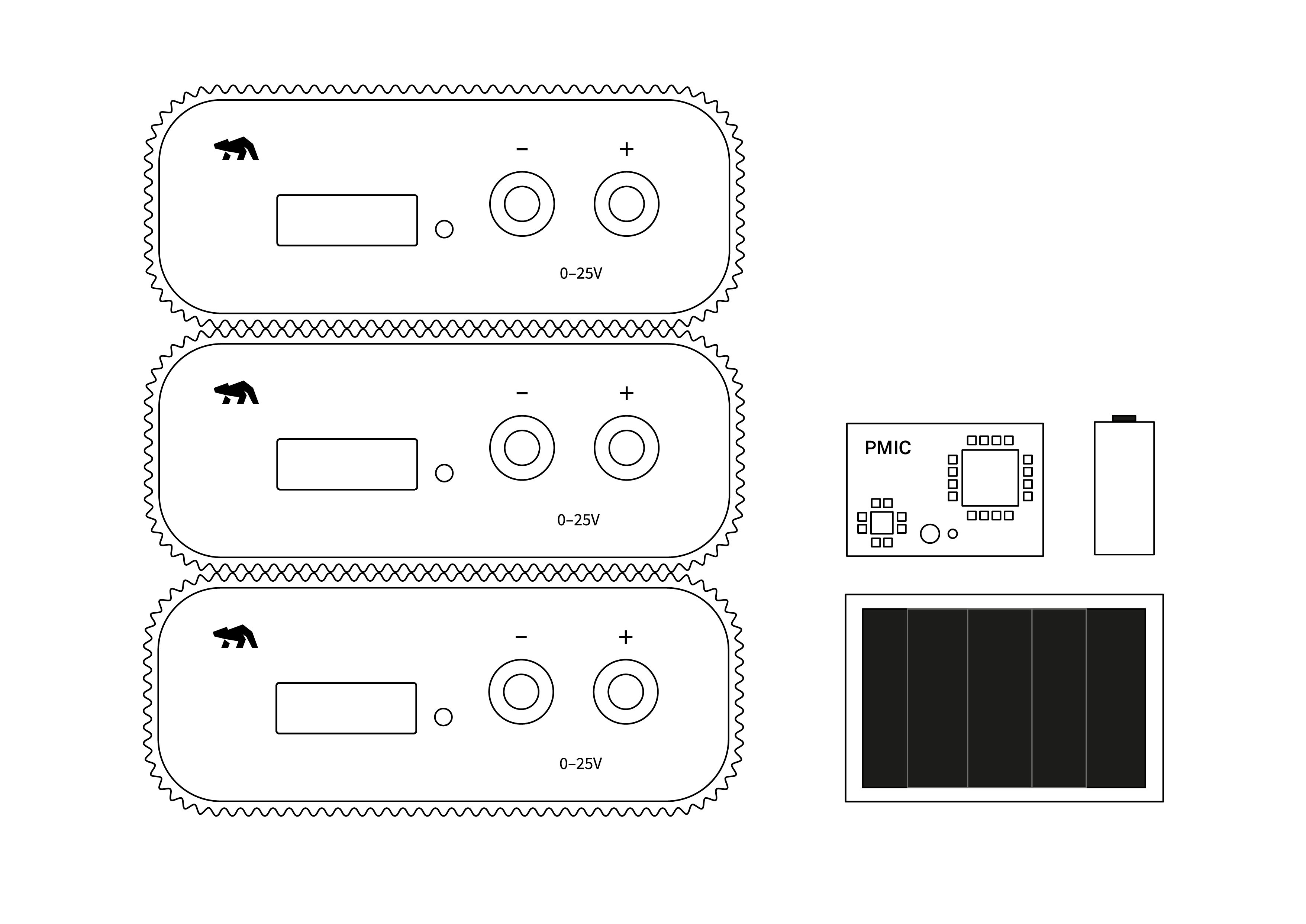
Products needed
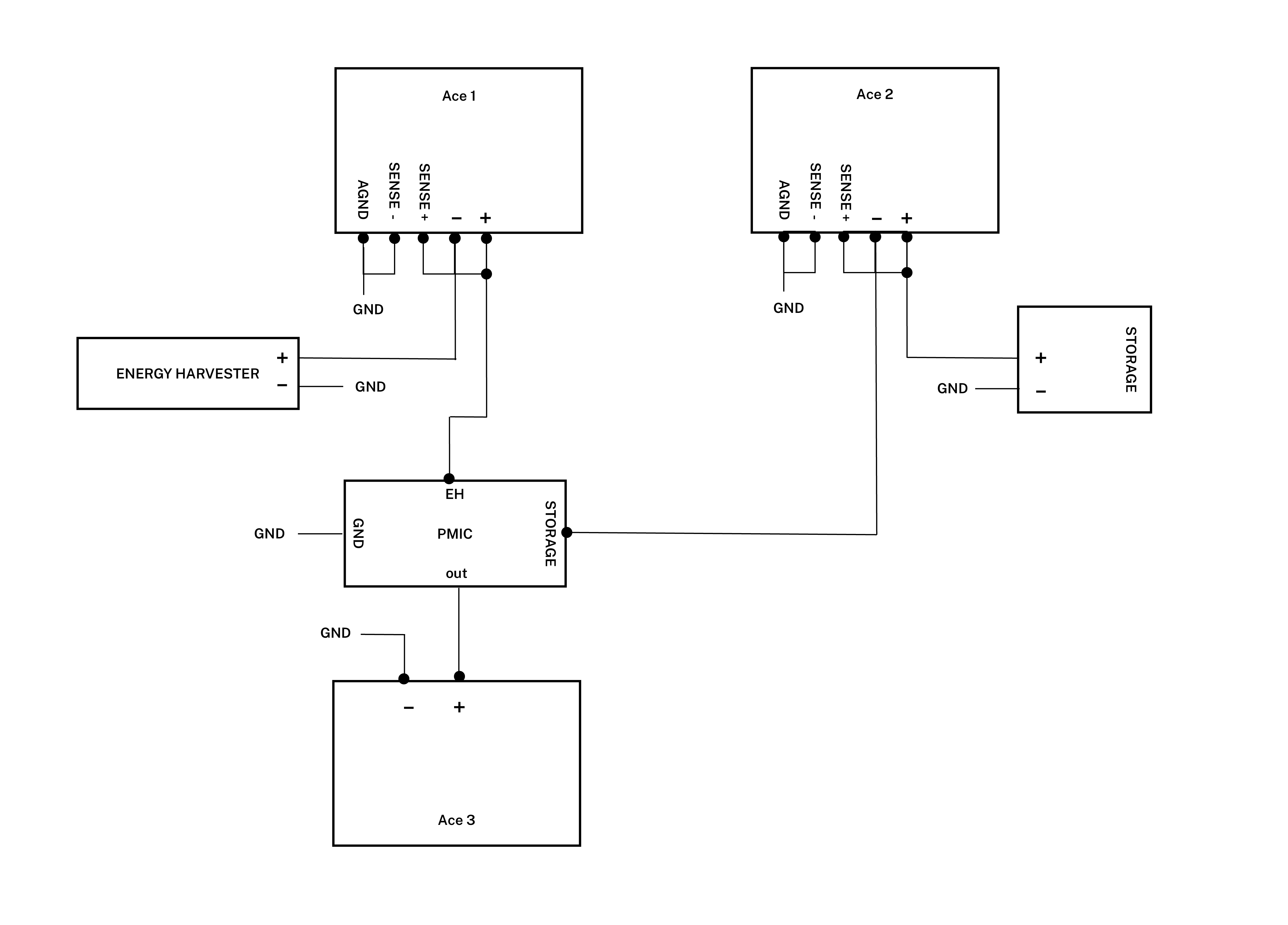
How to connect
- Connect Ace 1 banana connector – to PV cell output.
- Connect Ace 1 banana connector + and SENSE+ to PMIC PV cell input.
- Connect Ace 1 SENSE- and AGND to system GND.
- Connect Ace 2 banana connector – to PMIC energy storage input/output.
- Connect Ace 2 banana connector + and SENSE+ to energy storage positive pole.
- Connect Ace 2 SENSE- and AGND to system GND.
- Connect energy storage negative pole to system GND.
- Connect Ace 3 banana connector + to PMIC output.
- Connect Ace 3 banana connector – to system GND.
Get started in the Otii application
In general settings for Ace 1 and Ace 2, respectively:
- Set voltage for Ace 1 to something that doesn’t go over the OCV for the PV cell.
- Set voltage to nominal battery voltage on Ace 2.
In general settings for both Ace 1 and Ace 2:
- Change from “Power box” to “In-line” mode.
- Enable “4-wire” button. 4W will appear next to the voltage control of the Ace 1/Ace 2.
- Enable main current, main voltage and main power under Channels.
- Set wanted sample rate. Typically, 1000 samples per seconds is enough in this use case.
- Turn on power.
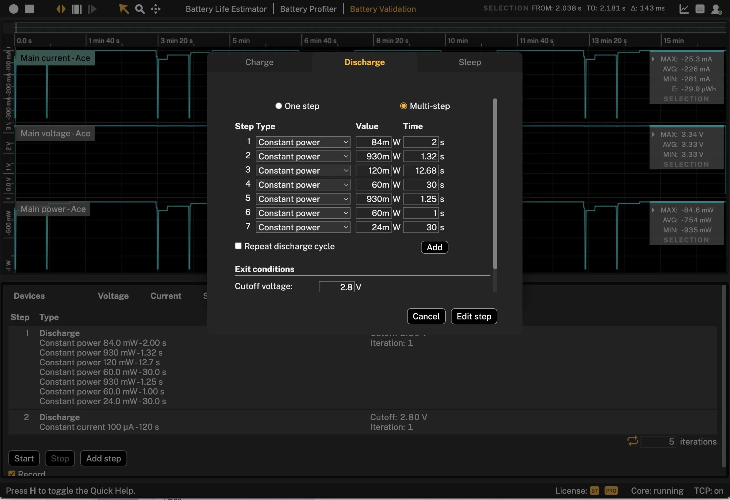
Set up the measurements:
- Select Battery validation.
- Set up a series of discharge steps, corresponding to both the IoT device active period and also sleep period.
- Enable Repeat discharge cycle, to repeat the above pulse.
- Select exit conditions of Cutoff voltage and optionally also number of Iterations or maximum Time.
- Click Add step.
- Under Devices in Battery validation, select Ace 3 only.
- Make sure that “Record” is selected.
- Click “Start” button.
Tips & tricks
 The Battery Validation discharge series can be stored in an Otii3 project so there is a possibility to change between different discharge patterns to emulate different protocols and different cycle times.A positive current/energy, for Ace 1 (photovoltaic) means that the energy harvester is generating energy into the system A positive current/energy, for Ace 2 (energy storage) means that the energy storage is charge. Ace 3 will have a negative current/energy since it is loading the system.