4-wire mode
Measure with 4-wire / Kelvin connection
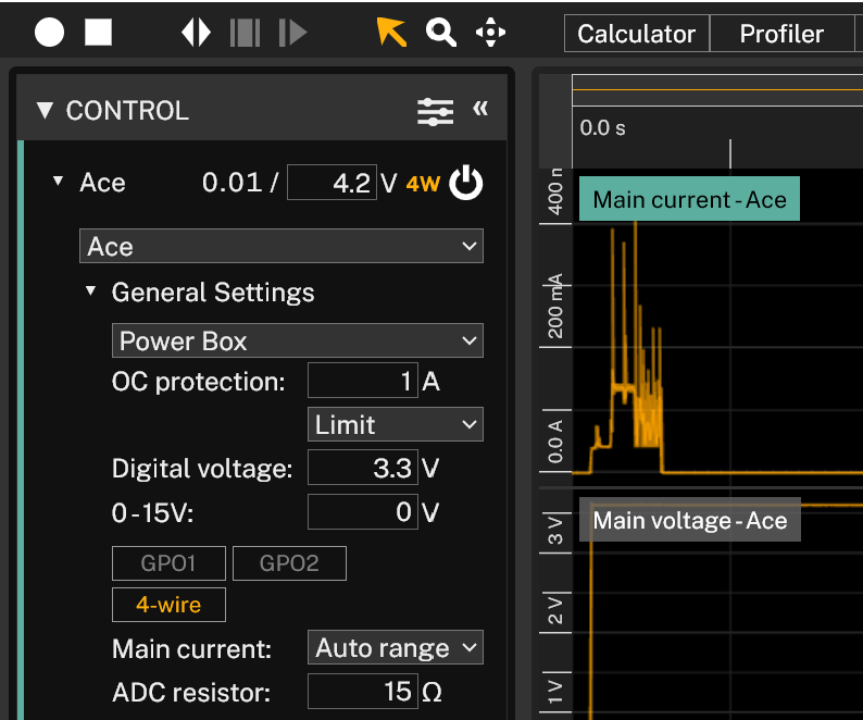
In 4-wire mode, also known as Kelvin connection, the voltage measurement (sensing) is separated from the power. The reason for separating the cables is that in the cables that also powers the Device Under Test (DUT) there will be a voltage drop, due to the cable resistance and the current. In the sensing cables, there is no, or very low, current, so there is very low voltage drop. When 4-wire is enabled, there will be 4W symbol highlighted next to the voltage measurement, to show that the voltage is measured from the SENSE pins.
In 4-wire mode, the regulated voltage will not be changed, only the measured voltage.
There are requirements on the SENSE pin measurement to have 4-wire active and they differ from Otii Arc Pro and Otii Ace Pro. For Arc, (SENSE+) must be withing 400mV from (Main+) and (SENSE-) must be within 400mV from (Main-), that also is GND. For Ace, (SENSE+) - (SENSE-) must be within 500mV from (Main+) - (Main-)
Products needed
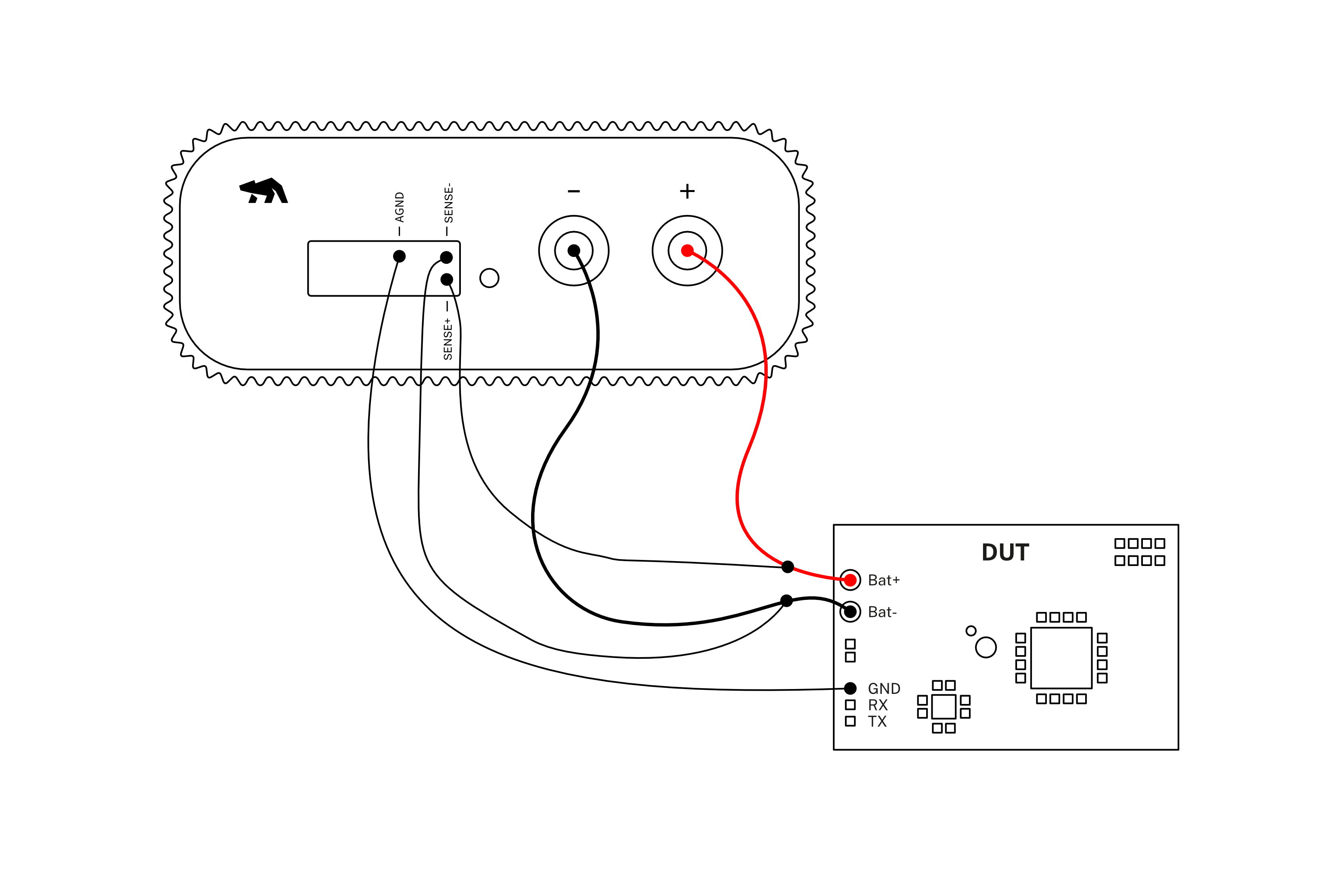
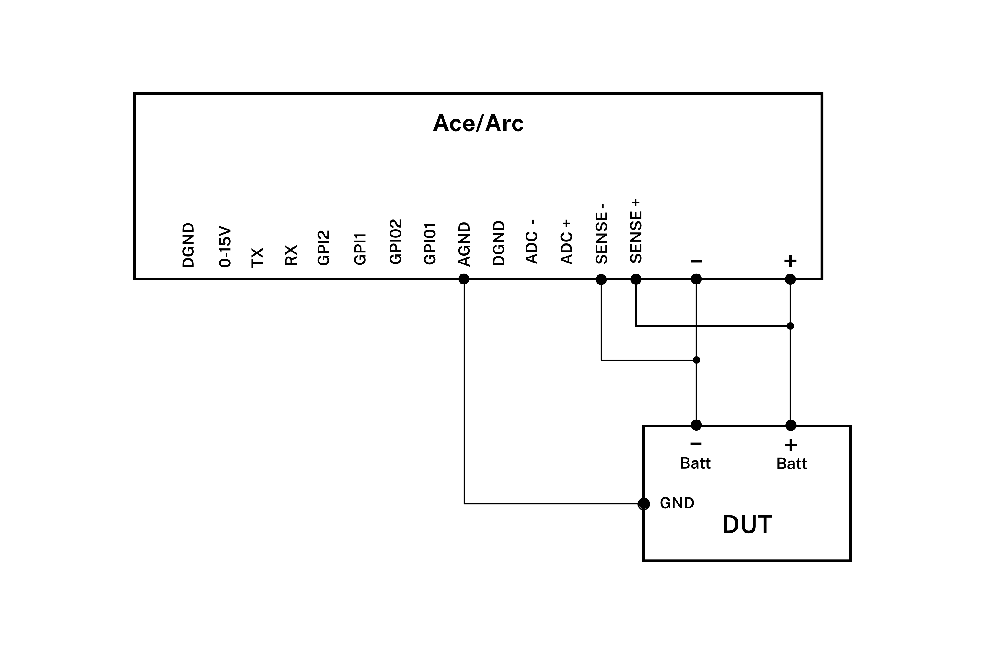
How to connect
- Connect Arc/Ace to your computer via USB. If needed, add a DC power supply via the DC plug.
- Connect Arc/Ace’s banana connector positive lead to DUT positive (+) battery connector/power connector.
- Connect Arc/Ace’s banana connector negative lead to DUT negative (-) battery connector/power connector (GND).
- Connect Arc/Ace’s SENSE+ pin to DUT positive (+) battery connector/power connector.
- Connect Arc/Ace’s SENSE- pin to DUT negative (-) battery connector/power connector (GND).
- Connect Arc/Ace’s AGND pin to DUT GND
Get started in the Otii application
- Add your Arc/Ace under Control in the sidebar. Rename it if desired (right click).
- Set-up the wanted voltage to supply your DUT with under Arc/Ace. Power box will be chosen per default. Add OC protection for your DUT.
- Under General Settings, make sure:
- Power Box option is selected.
- 4-wire is selected.
- Under ‘Channels’ choose what kind of measurements you want to record, for example main current, main voltage and main power. These will show as graphs.
- [Optional] The previously selected channels will be listed under the MEASUREMENTS section.
In this section, the sampling rate, up to
50 ksps, can be set. (Only possible with the Otii Ace Pro) - Start a recording. Your DUT is still not powered, and you will only see measured noise.
- Power the DUT by turn on the supply (On button) next to the Arc/Ace. The data from your DUT is now recorded.
- Now it's time to validate, analyze, and optimize your embedded system or IoT devices. The Main Voltage measurement is now from the SENSE pins, instead of the banana connectors.