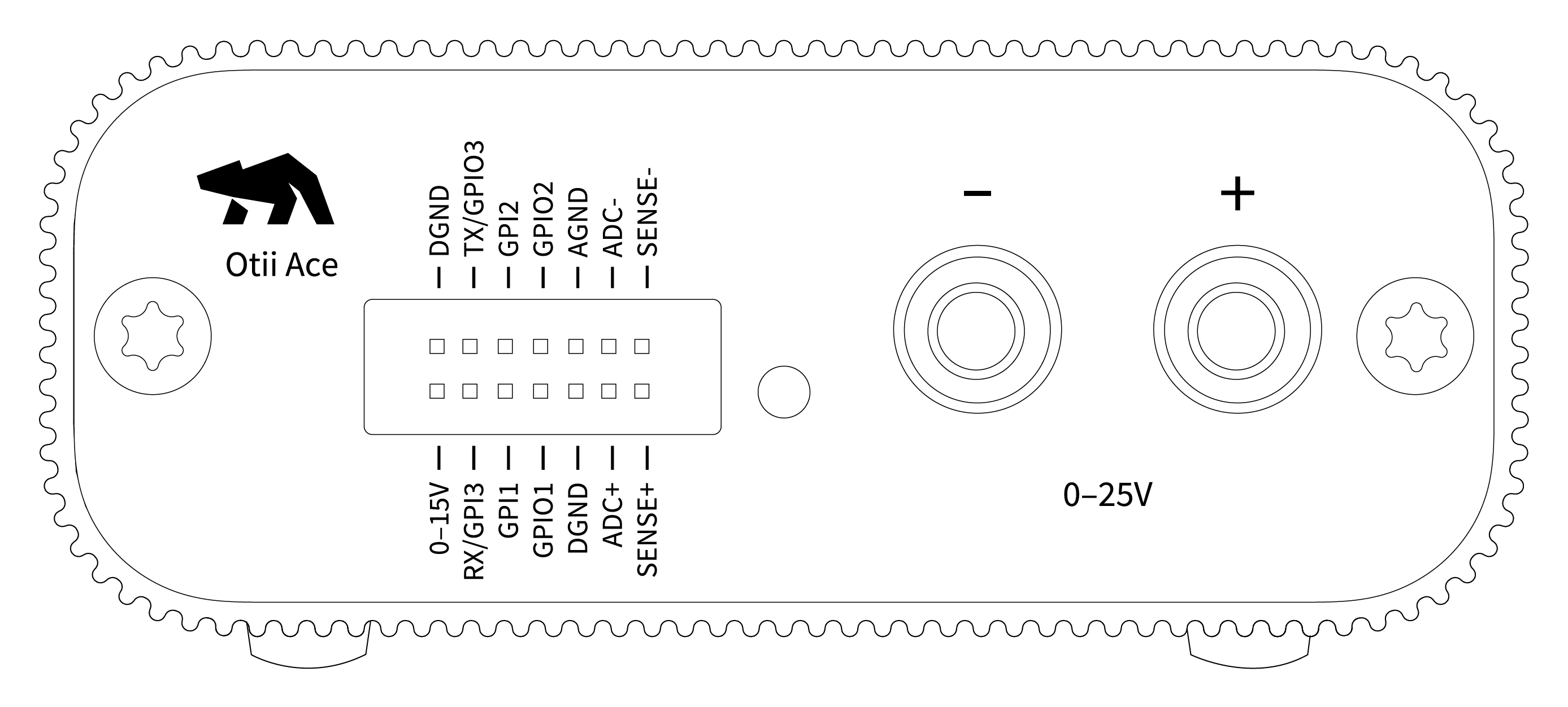
The front side of the Otii Ace Pro has the main connectors,
additional ports to extend measurement capabilities, plus a status LED.
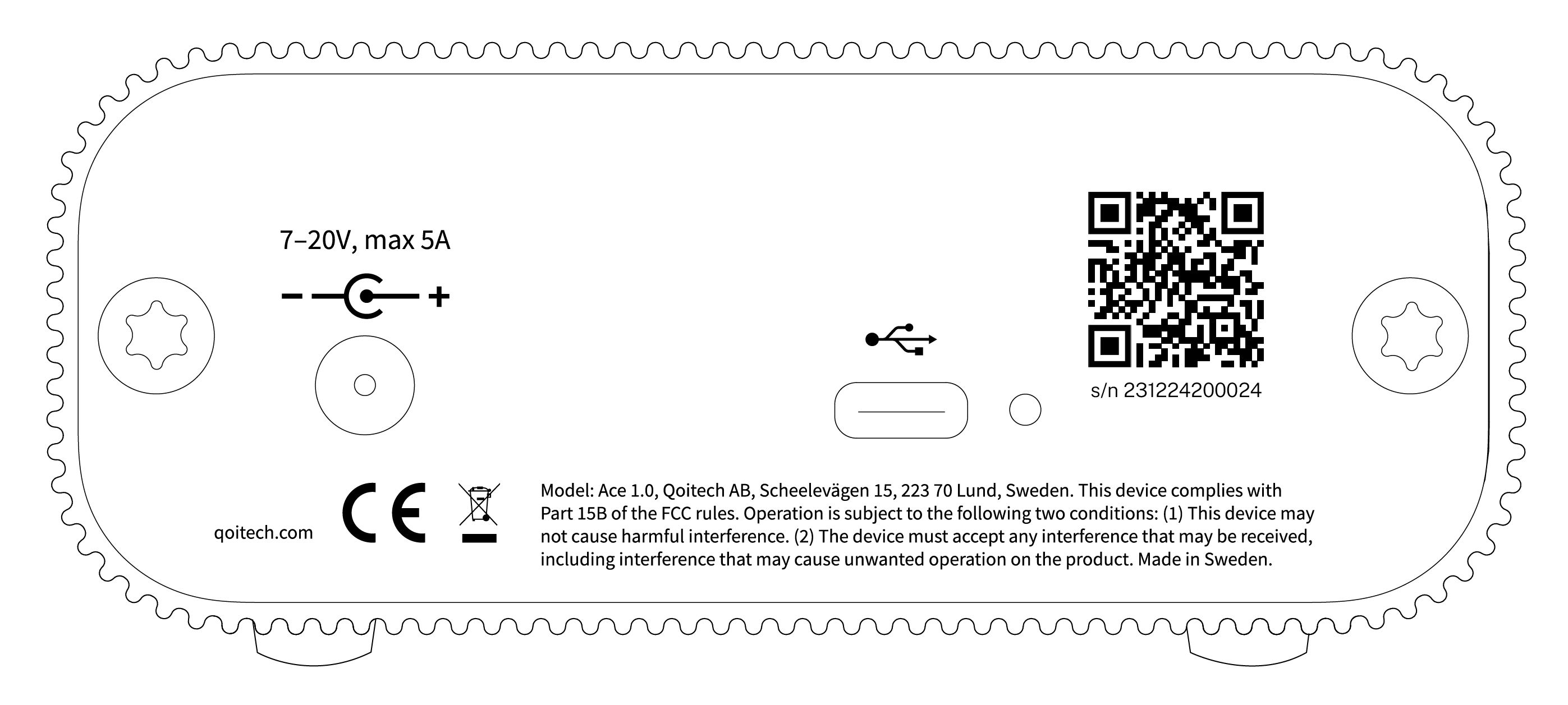
The back side of the Otii Ace Pro has the host USB connector and an input socket to power up
the unit with an external DC adapter when required.
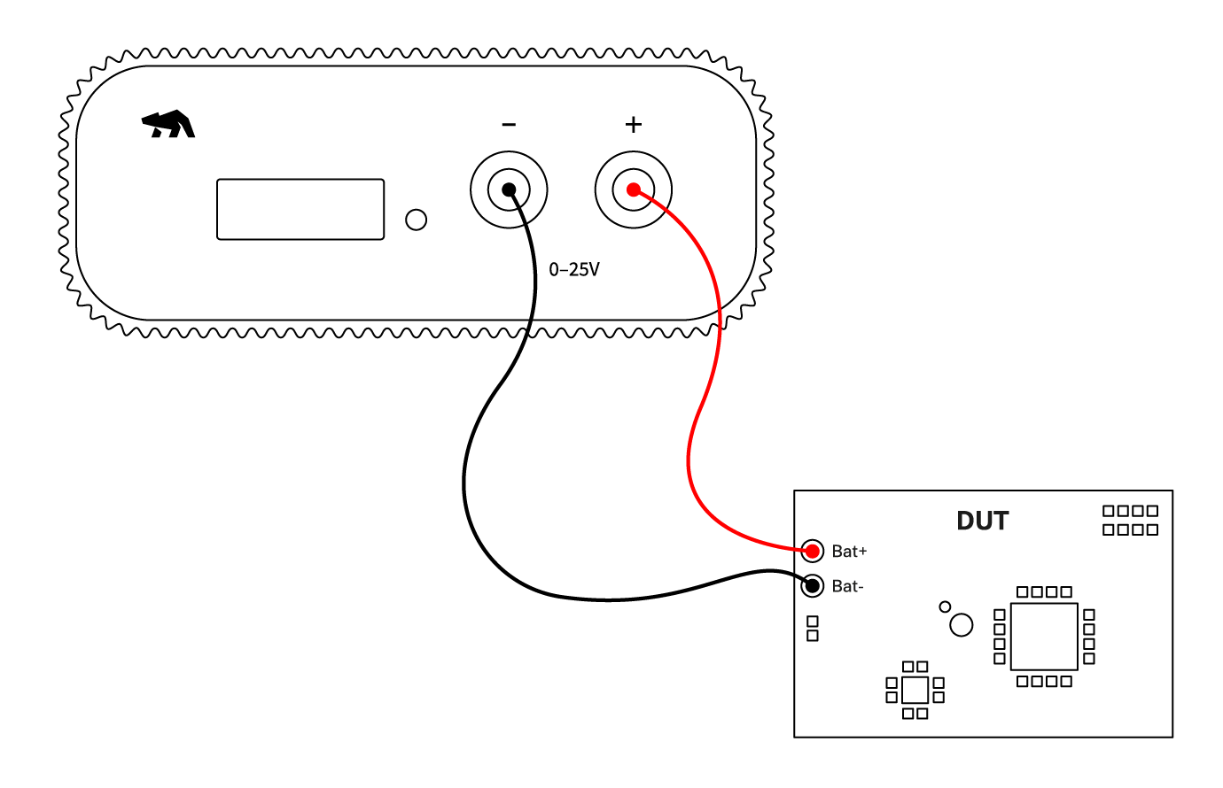
Main connections
The Otii Ace Pro has the voltage(+) and voltage(-) binding post (red and black connectors
located on the right side of the instrument), which are used to source the DUT but also to
measure the current, voltage, and power of the device.
The DUT can be connected through its battery connectors or DC input;
refer to the connection diagram below for better understanding.
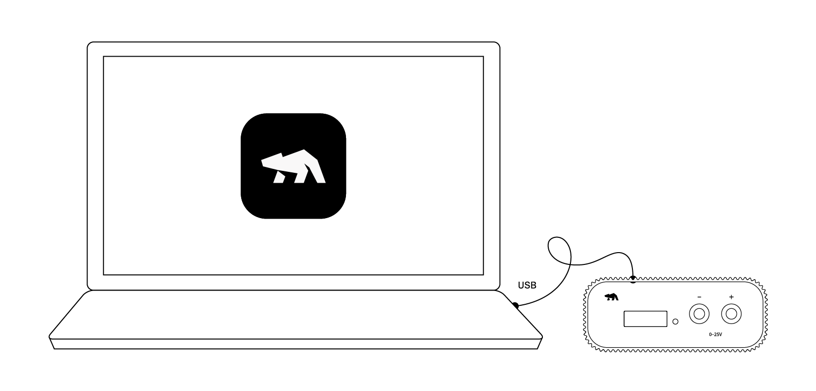
To power up the Otii Ace Pro and enable the communication with the host computer,
use the provided USB C cable to connect the unit to your computer.
Check out the Wiring up page to explore all possible connection configurations between
the Otii Ace Pro and your DUT.
Expansion Port
The expansion port on the front of the Otii Ace Pro is designed to enhance the hardware's
functionality, allowing users to measure additional voltages and currents or trigger
external events. These additional pins feature multi-input and multi-output for analog
and digital signals, serial communication, and additional power and ground points.
Below is a general overview of the additional pins available:
Connector
Description
Maximum rating
0-15V
Adjustable output between 0V and 15V
600 mA
DGND
Digital ground (return current)
RX
UART RX / Digital Input (Exclusively under Scripting)
0 V to 5.5 V
TX
UART TX / Digital Output (Exclusively under Scripting)
0 V to 5.5 V
GPI1
Digital input 1
0 V to 5.5 V
GPI2
Digital input 2
0 V to 5.5 V
GPO1
Digital Output 1
0 V to 5.5 V
GPO2
Digital Output 2
0 V to 5.5 V
DGND
Digital ground (return current)
AGND
Analog ground (return current) / Analog measurements
ADC+
Differential input for current measurement. It also measures single ended voltage with respect to AGND
-10 V to 25 V
ADC-
Input for current measurement
-10 V to 25 V
SENSE+
Analog input with the AGND as reference/return
-10 V to 25 V
SENSE-
Analog input with the AGND as reference/return
-10 V to 25 V
Status LED
The table below explains the Otii Ace Pro's status LED behaviors and their meanings to help you
quickly identify the device's state.
LED behavior
Otii Ace Pro Status
Solid blue
Otii Ace Pro is active
Solid green
Relay closed, sinking/sourcing power or in-line mode