Wiring up
Explore hardware setup examples for a variety of use cases.
Otii hardware features two main connectors and one expansion port. Multiple channels can be measured with the available inputs, such as main current, main power, main voltage, ADC current, ADC voltage, SENSE+ voltage, SENSE- voltage, GPI1, and GPI2, as well as capturing serial logs from any embedded system or IoT devices.
To get the most out of the Otii Arc Pro and Otii Ace Pro, start by checking out the Expansion port to explore how to enhance measurement capabilities.
Power supply
Otii instruments are powered via USB cable from the computer. Both Otii Arc and Ace Pro can be powered by an external DC adapter. When using an external DC adapter, choose one from an established supplier.
The adapter should be low-noise, comply with IEC 60950-1 as a Limited Power Source, and have an output of 7 to 9 VDC for the Otii Arc Pro and 7 to 20 VDC for the Otii Ace Pro, with a maximum of 5 A.
Visit the FAQ page for more information on selecting the proper power supply.
Grounding (GND)
We highly recommend to use a separate ground wire for the signal ground, attached to either DGND (Digital Ground) or AGND (Analog Ground) on the expansion port. This will prevent disturbances and measurement errors caused by voltage drops in the negative battery wire.
- AGND is utilized as a reference point for analog measurements
- DGND is used as a reference point for digital signaling
Measuring DUT
Power source and measure a Device Under Test (DUT).
Set up Otii hardware, either the Otii Arc Pro or Otii Ace Pro,
to work as a power source box providing constant voltage to the DUT,
ranging from 0.5 V - 5 V / 0 V - 25 V, and enable it to measure output current and voltage.
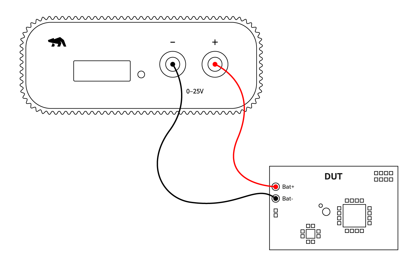
Otii hardware setup
- Connect Otii hardware to your computer via USB. If needed, add a DC power supply via the DC plug.
- Connect Otii hardware’s banana connector positive lead to DUT positive (+) battery connector/power connector.
- Connect Otii hardware’s banana connector negative lead to DUT negative (-) battery connector/power connector (GND).
 In case of connecting the DUT using the battery connector, remove the battery prior to connecting it to the Otii hardware.
Otii software setup
- Open the Otii 3 Desktop App, then select Create a new Otii Project
- In the left sidebar, find the CONTROL section. Within this section, add the Otii hardware identified by your computer. Just click the add button on the right side of the hardware identified.
- Considering the DUT's power ranges, set the required voltage for the added Otii hardware in the voltage box located on the left side of the power supply button.
- Under General Settings, make sure that the Power Box option is selected, and set an OC (overcurrent) protection for the DUT.
- Under Channels, select Main current to measure DUT's output current and Main voltage to measure DUT's output voltage. The Main power channel is assigned by default when the main current is selected to measure DUT's energy consumption.
- [Optional] The previously selected channels will be listed under the MEASUREMENTS section. In this section, the sampling rate, up to 50 ksps, can be set. (Only possible with the Otii Ace Pro)
- Click the record button in the upper left corner of the toolbar to start recording DUT measurements. Since your DUT is not powered on yet, only noise measurements will be observed at first.
- Turn on the DUT by clicking the power button next to the desired voltage assigned. Once turned on, the DTU measurements are being recorded.
- Now, it's time to validate, analyze, and optimize your embedded system or IoT devices.
 Use wires with the lowest possible resistance and keep them as short as possible to minimize voltage drop, especially when the DUT consumes high current. The resistance in wires will be added to the total series resistance within the system, causing an unwanted voltage drop and an error in power and energy consumption measurements.If the DUT consumes high current during power-up, causing high voltage drops in the attached wires, which directly affects the power-up cycle of the DUT since the voltage is too low. In case of experiencing this, connect one or several capacitors from Bat+ to Bat- on the DUT side to stabilize the voltage to start up the DUT properly. Note that the Otii Arc and Otii Ace have very low output capacitance for being a power source for the DUT but also a programmable load.
Measuring a subsystem
Power source and measures subsystem's current and voltage.
Set up Otii hardware, Otii Arc Pro, or Otii Ace Pro to measure a subsystem current and voltage over a shunt resistor in addition to measuring the complete system. Note that the resistor can be part of the actual system or applied externally.
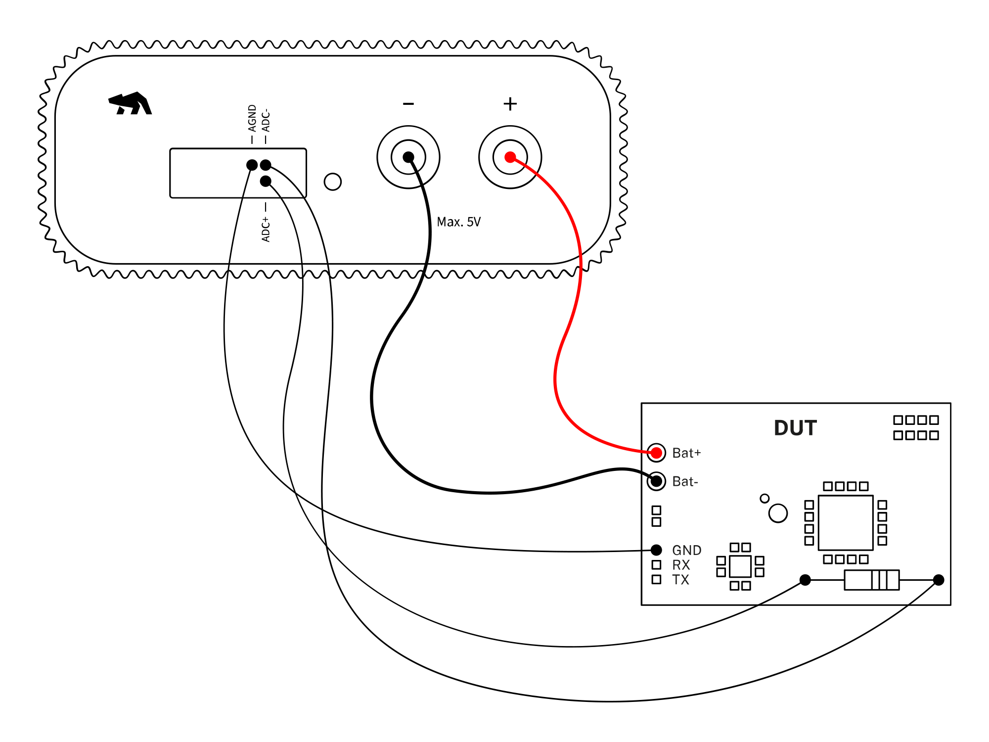
Otii hardware setup
- Connect Otii hardware to your computer via USB. If needed, add a DC power supply via the DC plug.
- Connect Otii hardware’s banana connector positive lead to DUT positive (+) battery connector/power connector.
- Connect Otii hardware’s banana connector negative lead to DUT negative (-) battery connector/power connector (GND).
- Connect Otii hardware's ADC+ and ADC- across the shunt resistor for current measurement; no additional ground is needed for this. Make sure to connect the shunt resistor side with the high side to ADC+ and the one with the low side to ADC-. Note that if negative currents are measured, the high side has a lower potential than the low side.
- [Optional] To measure voltage, connect AGND to the DUT's ground and measure the voltage between ADC+ and AGND.
In case of connecting the DUT using the battery connector, remove the battery prior to connecting it to the Otii hardware.Otii software setup
- Open the Otii 3 Desktop App, then select Create a new Otii Project.
- In the left sidebar, find the CONTROL section. Within this section, add the Otii hardware identified by your computer. Just click the add button on the right side of the hardware identified.
- Considering the DUT's power ranges, set the required voltage for the added Otii hardware in the voltage box located on the left side of the power supply button.
- Under General Settings, make sure:
- Power Box option is selected.
- Set an OC (overcurrent) protection for the DUT.
- Set the value of the shunt resistor in the ADC resistor field. Check how to choose the resistor if you are not sure how to do it.
- Under Channels, select ADC current to measure the subsystem current over a shunt resistor. In the case of measuring voltage, the "ADC voltage" must be selected as well. If the system itself needs to be measured, it can also be measured; select the channels desired to be measured in addition to the ones previously selected.
- [Optional] The previously selected channels will be listed under the MEASUREMENTS section. In this section, the sampling rate, up to 50 ksps, can be set. (Only possible with the Otii Ace Pro)
- Click the record button in the upper left corner of the toolbar to start recording DUT measurements. Since your DUT is not powered on yet, only noise measurements will be observed at first.
- Under the CONTROL section, turn on the DUT by clicking on the power button located right next to the desired voltage assigned. Once turned on, the DTU measurements are being recorded.
- Now it's time to validate, analyze, and optimize your embedded system or IoT devices.
The voltage over the shunt resistor is measured differentially. No extra signal ground is needed if you only want to measure the current.If voltage measurement is required, it is measured between ADC+ and AGND. In this case, AGND needs to be connected to the ground of the DUT.The maximum voltage range on ADC pins are 0 V to 5 V for Otii Arc Pro and -10 V to 25 V for Otii Ace ProHow to choose the resistor
For Otii Arc Pro
The differential input voltage range for the Otii Arc Pro ADC inputs goes from
-81.9175 mV to 81.92 mV. Based on these values, the absolute maximum (peak) current through
the sensing resistor must be determined.
Remember that by using Ohm's Law (V = I x R | I = V / R | R = V / I), the relationship
between voltage, current, and resistance in an electrical circuit can be determined.
Here's an example to illustrate how to choose the resistor:
Suppose the system has a maximum peak current of 200 mA. By calculating, 0.08192 V / 0.2 A,
the resistor value is equal to 0.41 ohms. But, the closest standard resistor value is
0.39 ohms. Resulting in a measuring range of 0.08192 V / 0.39 ohms = 0.210 A.
In conclusion, a 0.39 ohm sensing resistor will result in a measurement range of +/- 0.210 A.
For Otii Ace Pro
Following the same example as above, let's do the same for now but for the Otii Ace Pro.
The differential input voltage range for the Otii Ace Pro ADC inputs goes from
-102.4 mV to 102.4 mV. Based on these values, the absolute maximum (peak) current through
the sensing resistor must be determined.
Here's an example to illustrate how to choose the resistor:
Suppose the system has a maximum peak current of 200 mA. By calculating, 0.1024 V / 0.2 A,
the resistor value is equal to 0.512 ohms. But, the closest standard resistor value
is 0.51 ohms. Resulting in a measuring range of 0.1024 V / 0.51 ohms = 0.200 A.
In conclusion, a 0.51 ohm sensing resistor will result in a measurement range of +/- 0.200 A.
Ampere meter mode
Measures DUT's current and voltage while it is powered by an external power source.
If the Device Under Test (DUT) needs to be powered from an external source while still measuring system current and voltage, an external shunt resistor connected to the ADC inputs of the Otii hardware, whether the Otii Arc Pro or Otii Ace Pro, can manage this.
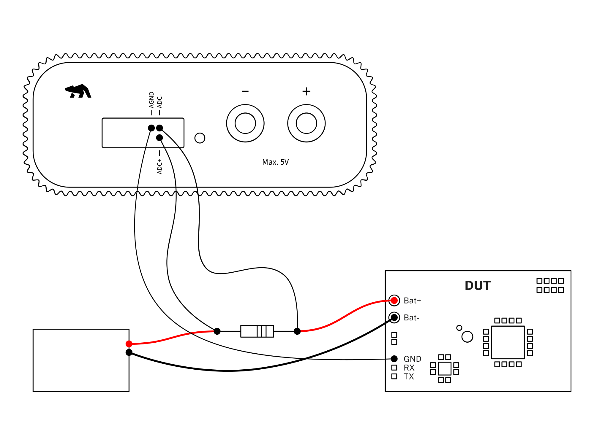
Otii hardware setup
- Connect Otii hardware to your computer via USB. If needed, add a power supply via a DC power adaptor.
- Connect the external shunt resistor in series between the external power supply's positive (+) line and DUT's positive (+) battery connector.
- Connect ADC+ and ADC- across the resistor to measure the voltage over the resistor.
- Connect Otii hardware's AGND to the DUT's GND.
Otii software setup
- Open the Otii 3 Desktop App, then select Create a new Otii Project.
- In the left sidebar, find the CONTROL section. Within this section, add the Otii hardware identified by your computer. Just click the Add button on the right side of the hardware identified.
- Under General Settings, make sure:
- Power Box option is selected.
- Set the value of the shunt resistor in the ADC resistor field. Check how to choose the resistor if you are not sure how to do it.
- Under Channels, select ADC current to measure the current over a shunt resistor. In the case of measuring voltage over the shunt resistor, the ADC voltage must be selected as well.
- [Optional] The previously selected channels will be listed under the MEASUREMENTS section.
In this section, the sampling rate, up to
50 ksps, can be set. (Only possible with the Otii Ace Pro) - Click the record button in the upper left corner of the toolbar to start recording DUT measurements. Since your DUT is not powered on yet, only noise measurements will be observed at first.
- Under the CONTROL section, turn on the DUT by clicking the power button. Once turned on, the DUT measurements are being recorded.
- Now it's time to validate, analyze, and optimize your embedded system or IoT devices.
The voltage over the shunt resistor is measured differentially. No extra signal ground is needed if you only want to measure the current.If voltage measurement is required, it is measured between ADC+ and AGND. In this case, AGND needs to be connected to the ground of the DUT.The maximum voltage range on ADC pins are 0V to 5 V for Otii Arc Pro -10V to 25V for Otii Ace ProCapture UART logs
Capture and record Device Under Test (DUT) serial logs.
Set up Otii hardware, Otii Arc Pro, or Otii Ace Pro to capture logs from the DUT serial log.
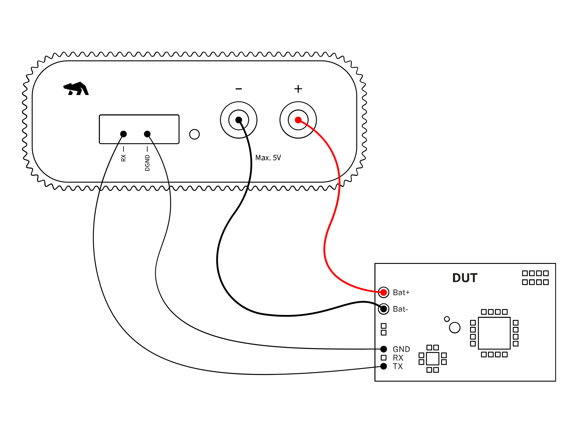
Otii hardware setup
- Connect Otii hardware to your computer via USB. If needed, add a DC power supply via the DC plug.
- Connect Otii hardware’s banana connector positive lead to DUT positive (+) battery connector/power connector.
- Connect Otii hardware’s banana connector negative lead to DUT negative (-) battery connector/power connector (GND).
- Connect Otii hardware's RX pin to the DUT TX pin.
- Connect Otii hardware's DGND to the DUT GND pin.
In case of connecting the DUT using the battery connector, remove the battery prior to connecting it to the Otii hardware.Otii software setup
- Open the Otii 3 Desktop App, then select Create a new Otii Project.
- In the left sidebar, find the CONTROL section. Within this section, add the Otii hardware identified by your computer. Just click the add button on the right side of the hardware identified.
- Considering the DUT's power ranges, set the required voltage for the added Otii hardware in the voltage box located on the left side of the power supply button.
- Under General Settings, make sure:
- Power Box option is selected.
- Set digital voltage according to the DUT's digital voltage level for the UART
- Set an OC (overcurrent) protection for the DUT.
- Under Channels, choose the measurements desired to be recorded (e.g., main current, main voltage, main power, among others)
- Under UART, make sure:
- Assign the DUT's baud rate.
- Select UART log to enable the serial communication. Once enabled, the console log will automatically open.
- Click the record button in the upper left corner of the toolbar to start recording DUT measurements. Since your DUT is not powered on yet, only noise measurements will be observed at first.
- Under the CONTROL section, turn on the DUT by clicking on the power button located right next to the desired voltage assigned. Once turned on, the DUT measurements are being recorded.
- Now it's time to validate, analyze, and optimize your embedded system or IoT devices.