Battery toolbox
 All these features require a Battery Toolbox License.
The Otii Battery Toolbox is a software license that extends the capabilities of the Otii Product Suite to enable battery profiling, battery simulation, battery testing and validation for low-power IoT devices and electronics.
The Otii Battery Toolbox license is:
- Associated with a user, not a specific piece of hardware.
- Sharable; a user can share it with another user, but it can only be used by one user at a time.
Using Otii Automation Toolbox, you can also configure a license pool that automatically shares the licenses among your battery evaluations setups. When using a shared pool, your test scripts can be configured to wait for a license to become available before execution.
Battery emulation
Otii can act as a battery, following a discharge curve. If you have reserved a Battery Toolbox license, a Supply section will appear in the Arc/Ace control settings. Press the Emulate battery button to open the battery emulation dialog. Choose the battery profile you want in the drop down list. A discharge curve will be shown for the chosen battery.
There are two curves, one shows the unloaded battery voltage over the used capacity and the other curve shows the internal resistance. Otii will adjust the output voltage depending on the load, just like a real battery with internal resistance.
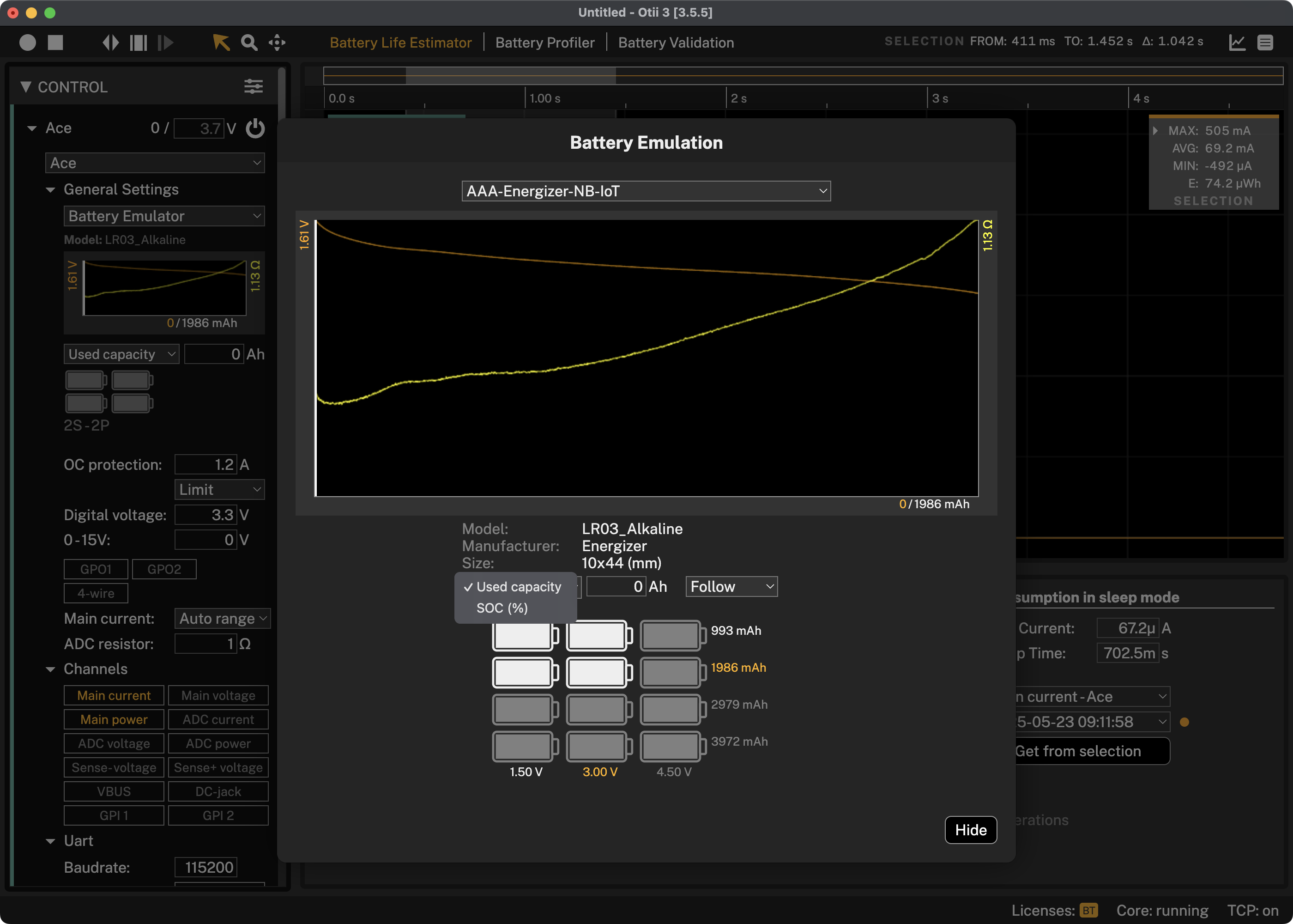
Used Capacity
Enter how many Ahs of the emulated battery's capacity that has been used if you selected Used capacity or how many percent if you selected SOC(%). To emulate a fresh battery, enter 0 for Used capacity and 100% for SOC(%).
Select Fixed to emulate the battery with a constant Used capacity as entered above. Follow will emulate a discharge over the time you are recording.
The rest of the settings are the same as when using the Arc as a constant power supply.
Series and Parallel
Click on a battery in the battery grid to set how many batteries in series and parallel to emulate.
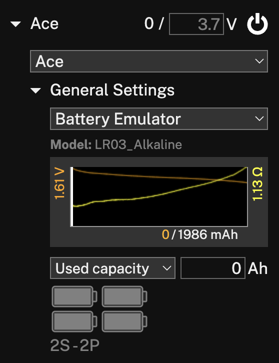
Hide
Press to hide the battery emulation dialog. Your current settings will still be visible in your Arc/Ace control settings, as displayed below. Here you can edit the used capacity or state of charge. To update other settings, press the curve to re-open the dialog.
Battery profiler
In addition to source current, the Arc can be set to sink current. E.g. by connecting a battery to the main connectors, you can test how the battery performs with different kind of loads.
To get started with battery profiling, choosing Battery Profiler from the toolbar will open the following pane:
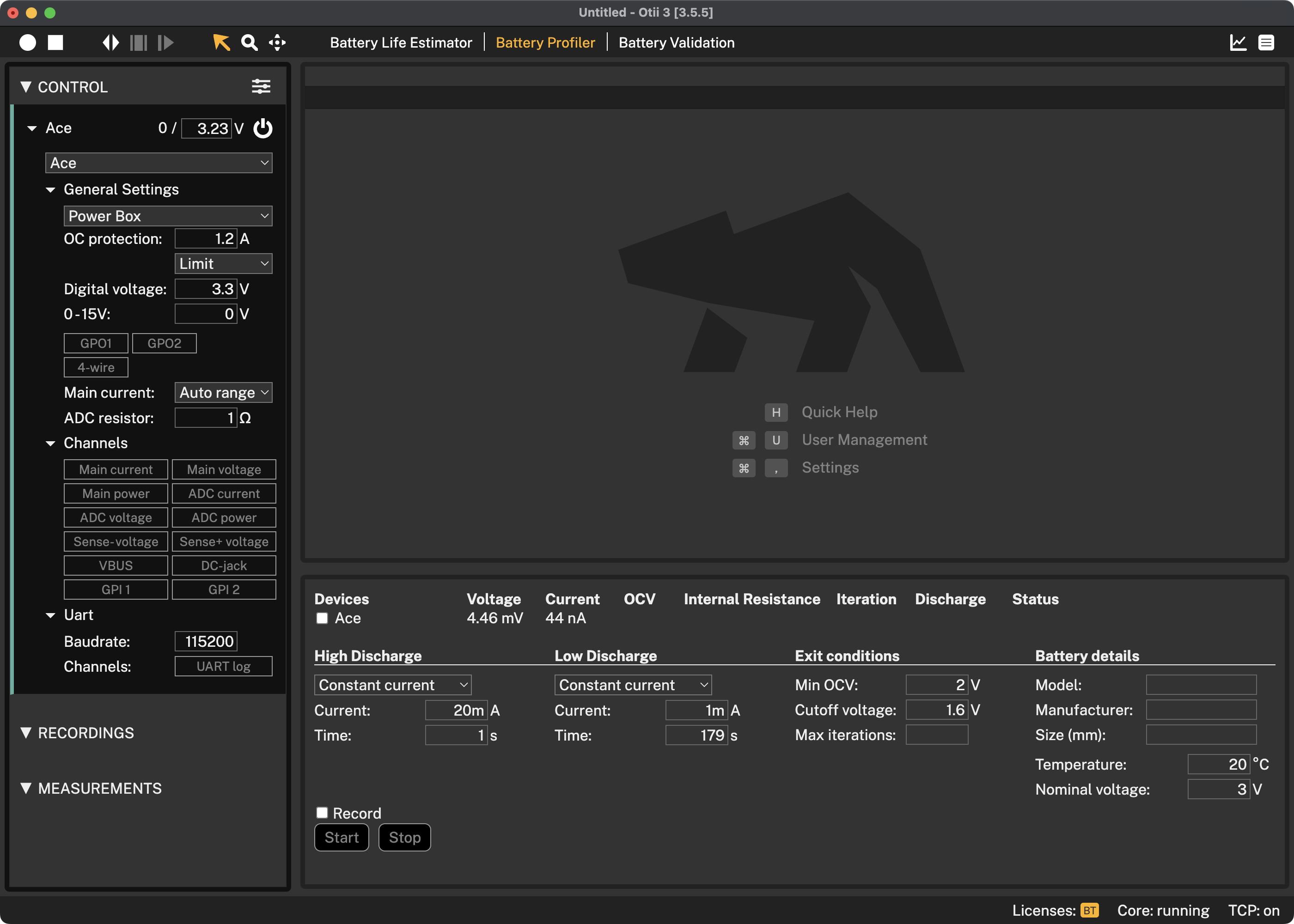
Devices
Here you choose which of your connected devices you want to use for battery profiling. When the profiling is running you will see some information of the current status of the profiling for each device.
Profiling Settings
Here you configure the profiling parameters, see more below on some best practices in choosing them.
You can also choose to automatically start a recording of the profiling. Recording the profiling session is optional, and for longer profiling sessions will require a lot of free space on your computer.
Battery Details
Here you enter the model, manufacturer and size of the tested battery.
Output
Scroll down the dialog to see a more detailed output from the profiling.
Start
Start is used to start a new profiling.
Stop
Stop is used to stop an ongoing profiling.
Save profile
When any of the exit conditions has been fulfilled, or the stop button has been pressed, a save button will appear after each device allowing you to save the profile for use in the battery emulator.

Getting started with battery profiling
- Connect the battery positive pole to the red banana connector (+) and the negative pole to the black banana connector (-)
- Start Otii 3 Desktop App, log in and reserve a Battery Toolbox license
- Open Battery Profiler tab
- Select the Otii Arc/Ace(s) that is going to profile the battery/batteries. It is possible to have several Otii Arc/Aces connected to the same computer to be able to profile several batteries at the same time
- Select if the discharge should be constant current/power or resistance for both the High Discharge and Low Discharge. This represent how your device draws energy from the battery. Typically, a LDO draws energy in constant current mode, a DC/DC in constant power mode and a resistive leakage in constant resistance mode.
- Input data for the High discharge and the Low Discharge period. This could be the active period and the sleep period of your device, how if draws the energy from the battery. There must be a difference in the High discharge and Low Discharge and High Discharge must be higher than Low discharge. This to be able to calculate the internal resistance of the battery.
- Input data for when the battery profiling is to be stopped, there are three possible exit condition and if one of them are met, then the profiling stops.
- Min OCV is the calculated Open Circuit Voltage (OCV) of the battery. It is not necessary to have a 0 load to be able to react on OCV as this is a calculated value based on the measured battery data.
- Cutoff voltage is the measured battery pole voltage
- Max iterations is if you would like to limit the number of iterations. If you do not want to limit the number of iterations, just leave this field empty
- Input the Battery details data like the module, manufacturer and size of the battery. This is just for your information, to remember what battery that was profiled.
- Input what temperature the battery was profiled in. It is good to have the battery profiled in the different temperatures that it will be subjected to in the real use case. Make sure to only put the battery inside the temperature chamber, not the Arc/Ace.
- Input the battery datasheet nominal voltage of the battery.
- Select if you want to have a recording ongoing during the battery profiling. This is not needed, the battery data is being measured anyways.
- Enable Main current and Main voltage channels and set wanted sample rate if a recording is wanted during profiling. Typically, the sample rate is set to 1000 samples per second as batteries has slow response.
- Click Start button to start the battery profiling and then wait for it to finish.
- When battery profiling has met an exit condition, the relay opens and a button “Save profile” appears. Click this to save the generated battery profile. The measured battery profiling data is also stored in the active project.
Why do I get internal resistance warning when profiling a battery
The internal resistance warning is a warning, so the profiling continues regardless.
The warning is that the internal resistance calculation ended up with a negative resistance. To understand this, the theory behind the internal resistance calculation needs to be understood.
Battery profiler discharges the battery with a high discharge pulse and a low discharge pulse. When the switch from high to low happens, the voltage (VH) and current (IH) is measured . Then when the switch back from low to high happens, the voltage (VL) and current (IL) is measured. The internal resistance is then calculated by Ohms law Rint = (VL-VH)/(IL-IH) The currents are negative. If the battery has a lower voltage in the end of the low discharge, than the voltage at the end of the high discharge, Rin will be negative.
To avoid this do the following:
- Have a shorter cycle time
- Have a higher difference between high and low current
Battery Validation
Battery Validation requires an Otii Ace Pro.Battery Validation provides a comprehensive view of your battery by monitoring its performance in various scenarios. You can charge and discharge the battery in one or multiple steps, repeat discharge cycles, and create custom scenarios.
To start using Battery Validation, select Battery Validation in the toolbar
or press Ctrl-T / Cmd-T combination. A panel will then appear where you can view
and modify the validation configuration.
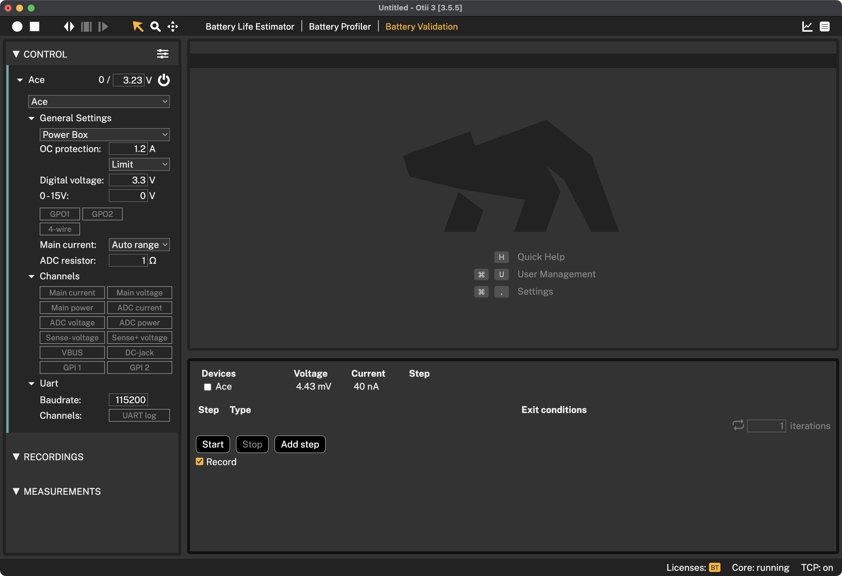
Devices
Here you will see a list of connected devices where you can pick which of them you want to use for battery validation.
Start
To start battery validation, press Start.
Stop
To stop battery validation, press Stop.
Record
You can optionally record the ongoing battery validation session by selecting Record.
Add step
Press Add step to open the battery validation dialog.
Discharge step
The discarge step function is splitted by One step and Multi-step.
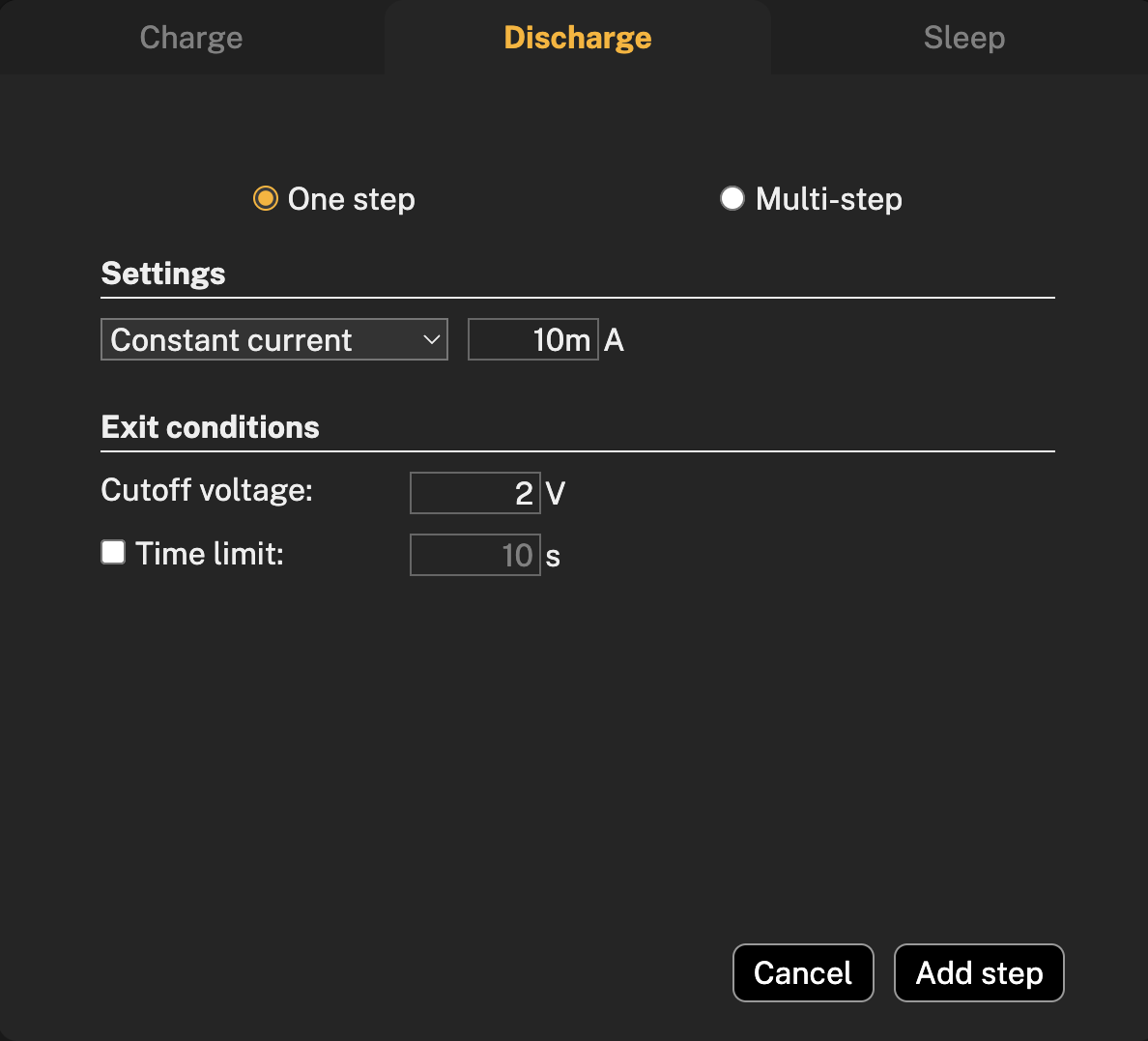
One step
One step allows you to have a discharge step without specifying max time.
Settings
In the settings you can pick between Constant current, Constant power or Constant resistance and insert you value, acording bto the battery under the test.
Exit conditions
The exit conditions for discharging a battery are the conditions under which the battery should be stopped from discharging to prevent damage to the battery. Cutoff voltage means setting a minimum voltage below which the batterry is not allowed to discharge. Check battery datasheet for this information. Time limit is optional in case of One step discharge, but recommends in case if the battery is discharging at a very low current and the voltage cutoff may not be triggered, also to prevent overdischarging or other unexpected behaviours.
To add step, press Add step button and the configured step will appear in the dialog.
Multi-step
A multi-step battery discharge involves discharging the battery in several steps, each with a different constant current, power, or resistance profile, depending on the desired outcome and battery type.
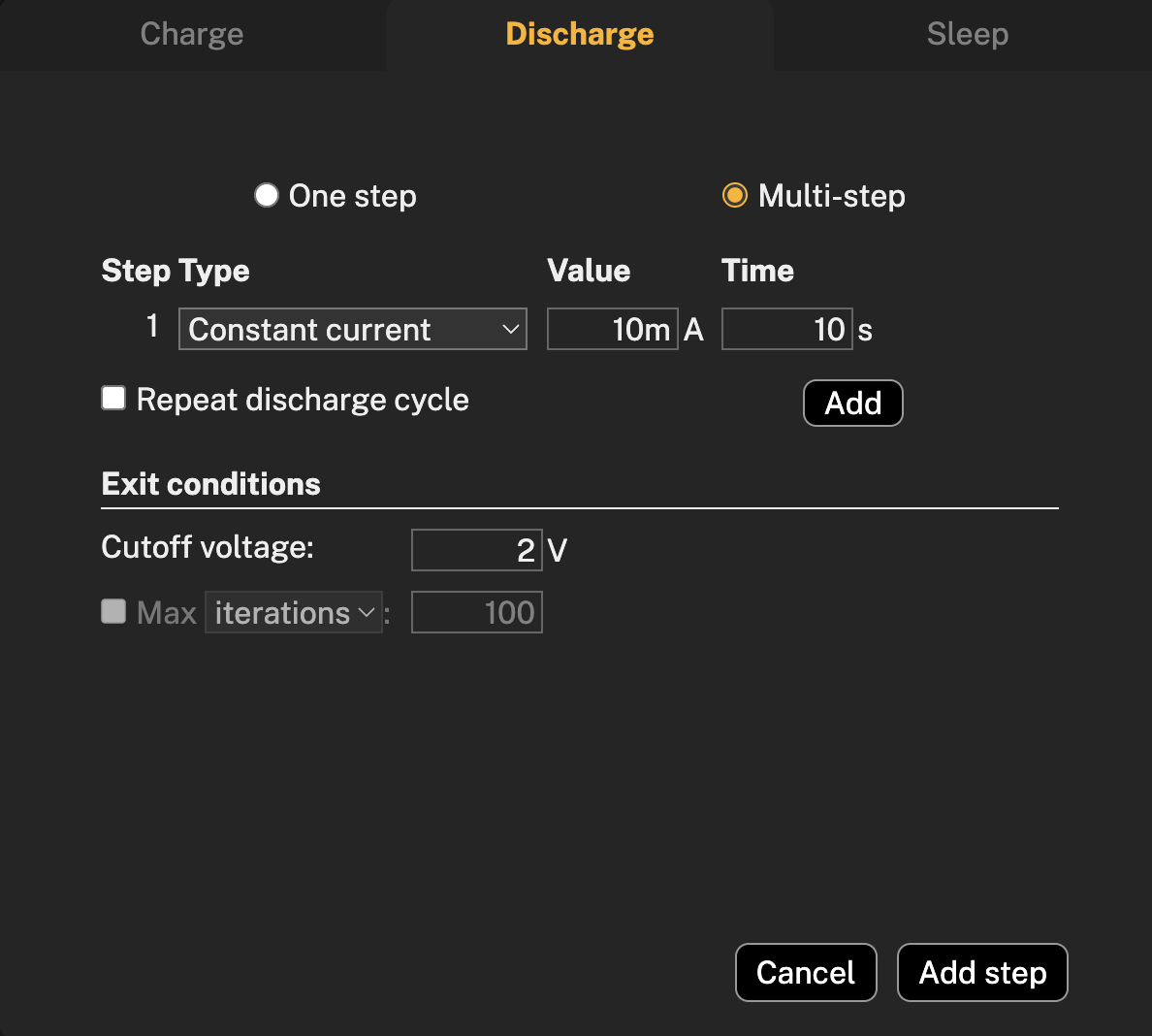
Step type
To create a profile with several step types for battery discharge, select the desired step types and configure the parameters for each step, including time, and press Add to add more steps. It is also possible to repeat discharge cycle by selecting Repeat discharge cycle.
The exit conditions in the multi-step discharge, besides cutoff voltage that works same principle as in one step discharge, contains a checkbox where in case if you decide to have repeated discharge cycle, you can choose between Max iterations or Max time.
To add multi-steps, press on Add step button and configured multi-steps will appear in the dialog.
Charge
A battery charging test is often used to evaluate a battery design to see if it meets its performance and safety specifications.
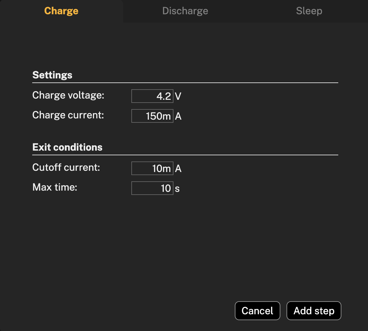
Settings
Before charging the battery, make sure to set up the settings according to the documentation of the tested battery, which is includes Charge voltage and Charge current.
Charge voltage is the voltage applied to a battery to overcome its internal resistance and charge it. It is typically higher than the battery's nominal voltage.
Charge current is the electric current that flows into a battery while its being charged. It's also very dependent on the type of battery, and before setting up the value, check the datasheet of the battery under test.
The exit conditions of battery charging are the Cutoff current and Max time of charging the battery.
Cutoff current is the current at which a battery will stop charging; this prevents battery's overcharging.
Max time is the longest amount of time that a battery will be charging. This ensures that the battery is not being overcharged.
Battery types will have a different cutoff current and maximum charging time, so make sure to read the documentation first.
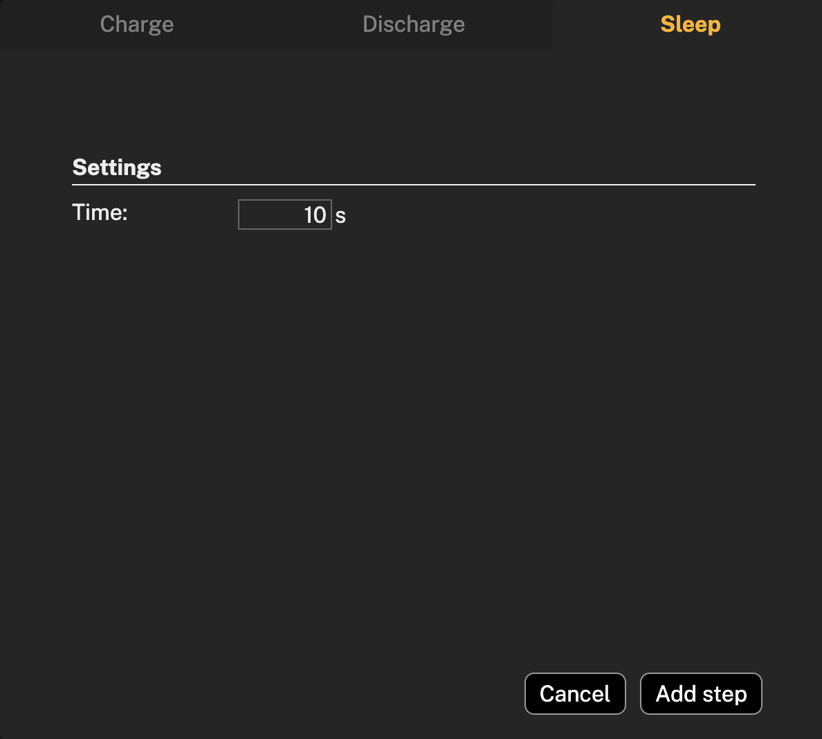
Sleep
Due to different battery types and their chemistry, battery temperature and protection security it is important to have a time sleep between charging/discharging steps. To set up sleep time between selected steps, swich to the Sleep tab and set up desired sleep time. Press Add step.
Battery model parameters
| Battery model parameter | Otii Arc Pro | Otii Ace Pro |
|---|---|---|
| Points in Emulation | as many as no of iterations | as many as no of iterations |
| ESR Range15 | up to 5 kohm | up to 5 kohm |
| ESR Resolution | down to 1 mohm | down to 1 mohm |
| Voc Range | 0.5 V to 5 V | 0 V to 25 V |
| Voc Resolution | 1 mV | 1 mV |
| Capacity Range | no limit | no limit |
| Capacity Resolution | 1 µAh | 1 µAh |