Control
The Otii 3 Desktop App has a control panel on the left sidebar that facilitates the connection between the Otii hardware and the application, assuming it is correctly connected to the computer.
The CONTROL section enables the Otii hardware to be set up according to the technical parameters of the devices under test (DUT), the mode of use of the Otii hardware, and the channels to be measured. These configurations are independently set for each connected Otii hardware, regardless of whether it is an Otii Arc or Otii Ace.
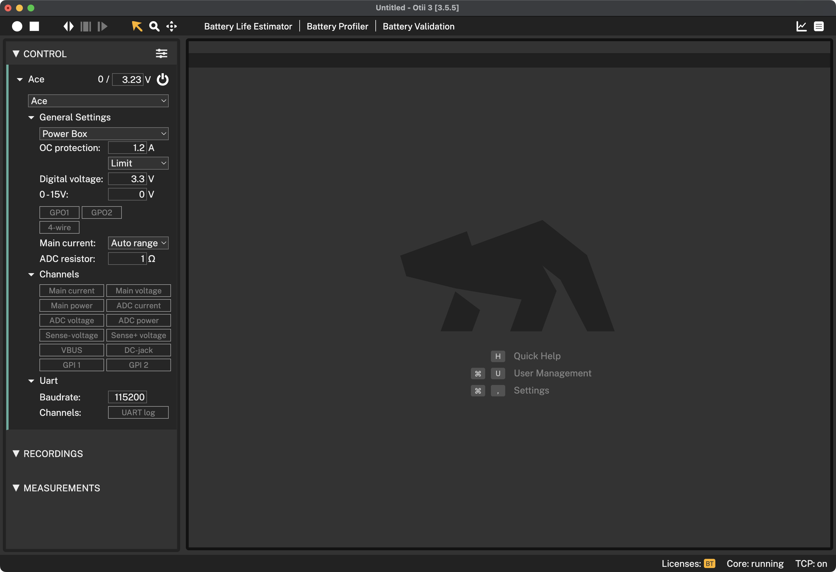
As shown in the image above, the CONTROL panel features the following:
- Arc/Ace: Define power supply voltage, and it turns ON/OFF
- General settings: Set the operation mode for the Otii hardware and define the settings in which it will operate based on the DUT's characteristics
- Channels: Channels available for measurement by the Otii hardware
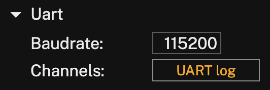
- Uart: Enable and set up serial communication with the DUT for debugging
Control filter
To filter what is being shown in the control list, click the filter button just next to the control title:
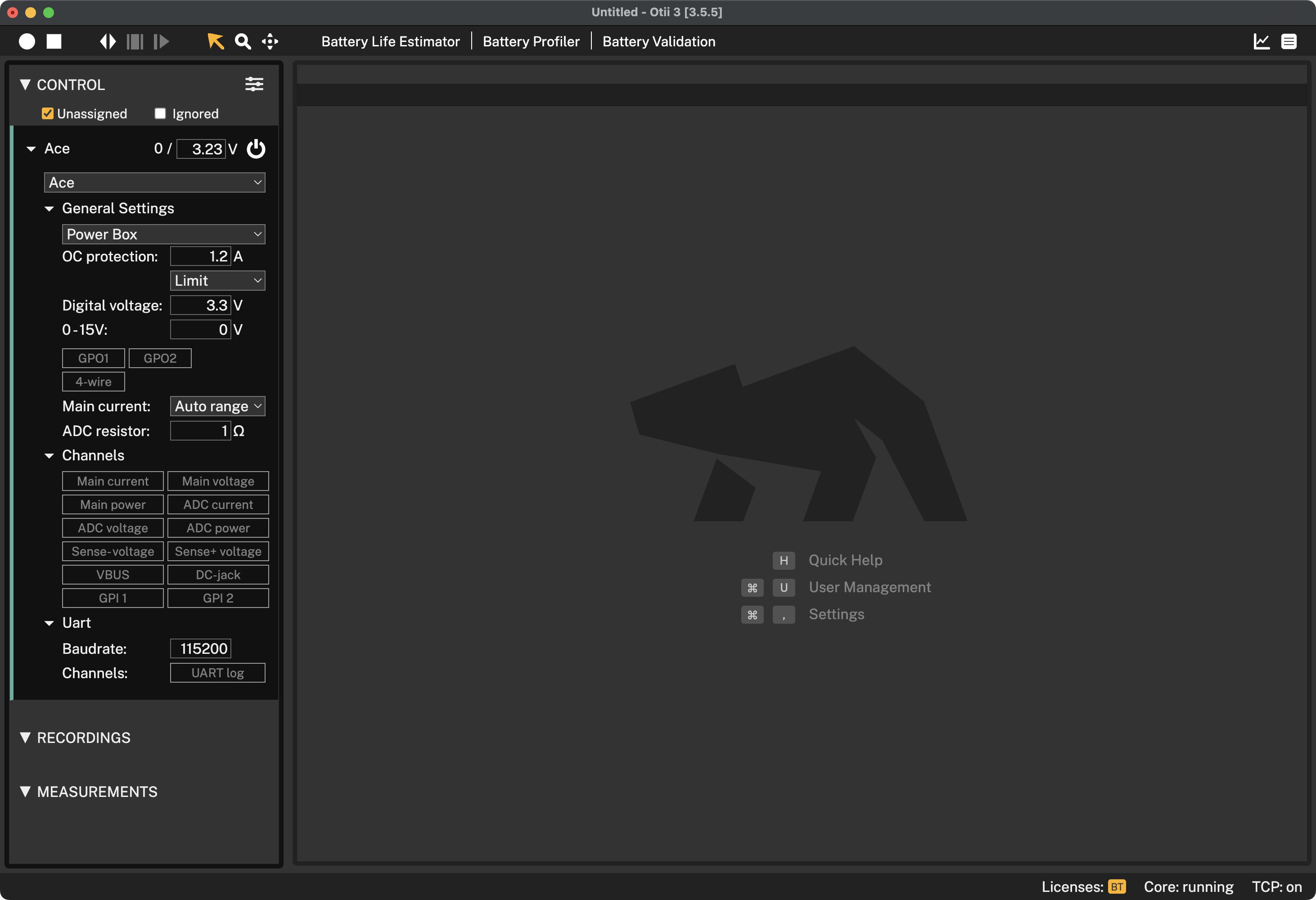
Where,
- Unassigned: When enabled, all devices, including those that are not added to the project, will be shown
- Ignored: When enabled, it will show ignored devices. UART devices can be ignored by right-clicking it and choosing Ignore
Otii Arc and Ace setup
After connecting the Otii hardware (either the Otii Arc or Otii Ace) to the computer is automatically recognized within the Otii 3 Desktop App. To add it, click the Add button.
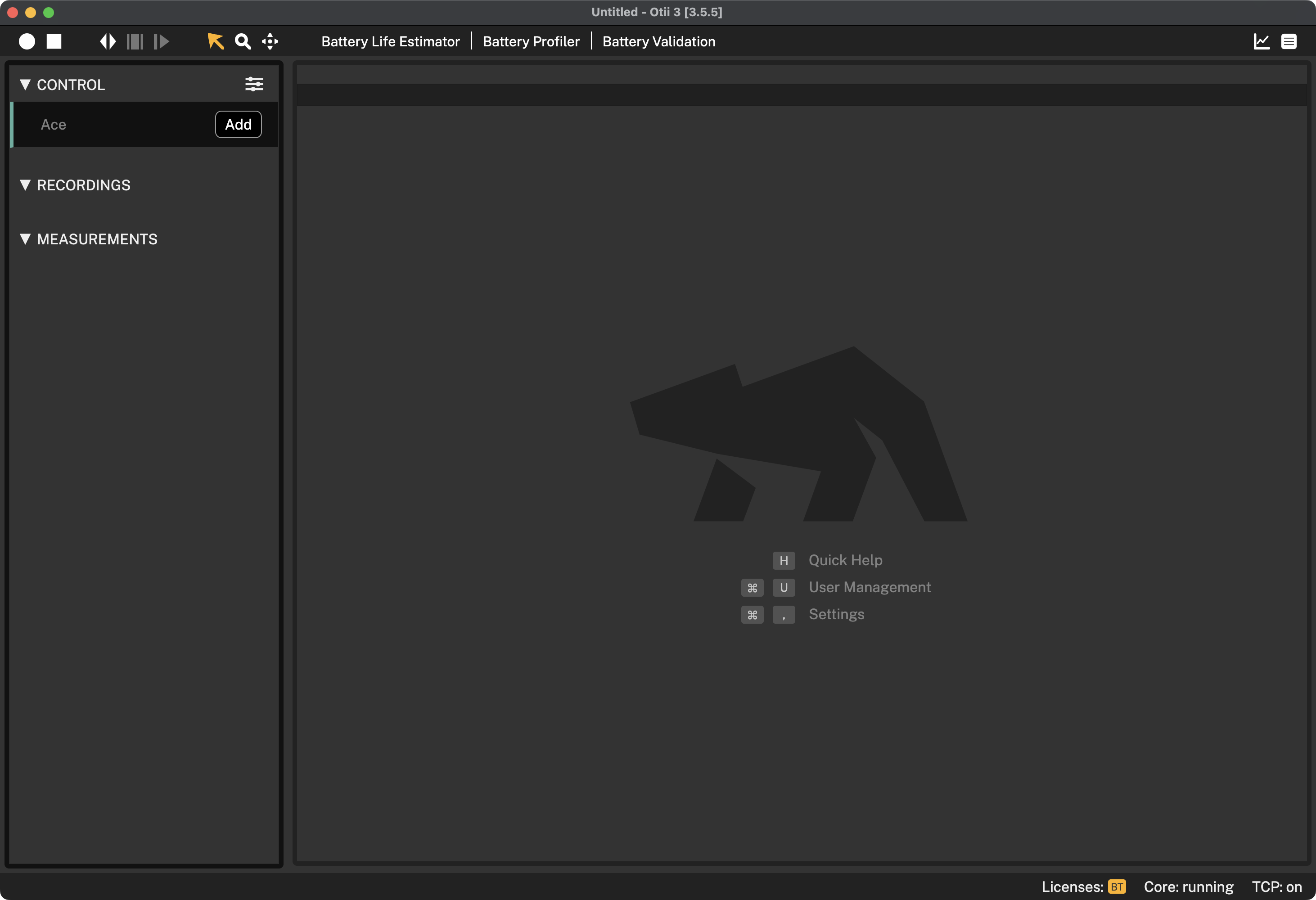
By default, once the project is saved, the Otii hardware will be added to it each time it is opened. Once added, users can set up and/or customize the following parameters:
Name
By default, the name given to the device is the version of the Otii hardware used. To change it, double-click and assign the desired name, or right-click, select Rename, and assign the new name.
Main voltage
Just right next to the Otii hardware name, the measured voltage followed by the desired voltage will be found. Being the desired voltage, the one supplied through the Otii hardware main terminals when the unit is set in Power Box mode.
By default, the voltage assigned to the Otii hardware, either Otii Arc Pro or Otii Arce Pro, is 3.0 V. To change it, click on the value and enter the new desired voltage. Keep in mind that the Otii hardware's main output range for the Otii Arc Pro is 0.0 V — 5.0 V, and for the Otii Ace Pro is 0.0V—25.0V; however, the system restricts the max output to 0.0V—5.5V. When using Otii Ace Pro, the max voltage can go up to 25.0V. To change it, go to Settings > Max supply voltage and set the desired maximum voltage.
 The maximum voltage that Otii Arc Pro can supply depends on whether a power supply via the DC plug is connected to the Otii hardware and whether activating the "Auto range" option is selected as the main current parameter. The maximum value will be automatically updated based on the current configuration.
 Make sure to cap the max voltage based on the DUT's technical requirements to avoid accidental high voltages.
Power button
Click the power button to turn the main power supply ON/OFF.
Device attachment
The drop-down box below the Otii hardware name enables the control settings to be reassigned to another Otii hardware of the same version. To do so, select and reassign the other Otii hardware(s) within the list.
An Otii Arc Pro cannot be reassigned with an Otii Ace Pro or vice versa.General settings
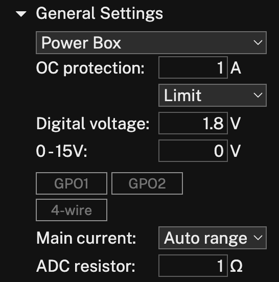
Supply mode
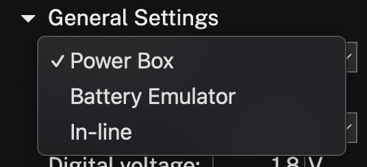
- Power Box: The Otii hardware will supply a constant voltage to the Device Under Test (DUT)
- Battery emulator: Otii hardware will emulate a battery. (Only available with Battery Toolbox)
- In-line: This particular mode is exclusive to the Otii Ace Pro version. It works like an ampere meter by being in-line between the power source and the DUT. The Otii Ace Pro automatically switches between different measurement ranges but provides no power. To also measure voltage, 4-wire must be enabled
Over current protection
The OC current protection setting allows users to set a maximum current limit that the Otii hardware can supply. For the Otii Arc, if the current exceeds the assigned limit, the unit will switch OFF the main supply to protect the DUT.
Within the dropdown, choose among the available options how the current limits must be detected, along with expected device behavior:
- Limit: enabled for Otii Arc Pro and Otii Ace Pro, it limits the output current to the set current, lowering the output voltage
- Cut-off: enabled only for the Otii Arc Pro, it detects when the current exceeds the set current to turn the power OFF and open the output relay.
Digital voltage
The digital voltage setting allows the output voltage desired for the pins available within the expansion port to be set up. Also, depending on the digital voltage setting, the level for deciding if it is a logical 0 or 1 is also changed.
Some configurations in this section differ based on the version of Otii hardware used.
Otii Arc Pro
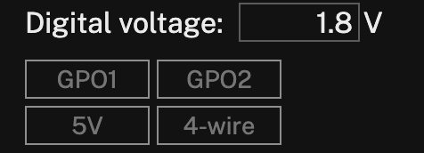
- GPO1 & GPO2 - enable digital outputs
- 5 V - enables an additional fixed 5 V output
- 4-wire - enables 4-wire measurements to compensate for voltage drop in the power supply leads
Otii Ace Pro
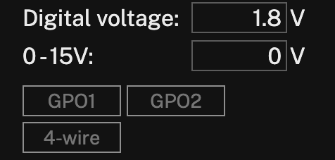
- 0 - 15 V - Enables an additional voltage output ranging from 0 to 15 V
- GPO1 & GPO2 - enable digital outputs
- 4-wire - enables 4-wire measurements to compensate for voltage drop in the power supply leads
Main current
The main current enables the Otii hardware to switch automatically between the different measurement intervals.

- Auto range: when selected, the highest available measurement accuracy interval is selected
- High range: when selected, it prevents the Otii hardware from going to the lowest measurement range
Therefore, there is no switch in or out of the shunt resistor
- Use this setting if the device resets when the **Otii hardware switches measurement interval
- Use this setting if higher voltage output is needed for Otii Arc Pro, as the voltage drop internally within this Otii hardware version is lower
Otii Arc cannot supply above 3.75V in USB mode and 4.55V when supplied with DC plug when selecting auto range. In high range, it can supply 4.2V in USB mode and 5.0V when supplied with DC plug. Note, Otii Ace can supply the full voltage range both in USB mode and when supplied with DC plug.ADC resistor
When using the ADC pins to measure the current of a specific system, an external shunt resistor is required. Therefore, the resistance must be set. To ensure that the resistor impedance is set correctly, refer to the Measuring a subsystem example; this example will guide you through connecting the DUT to the ADC connectors and setting the impedance of the resistor.
Channels
Channels in the Otii 3 Desktop App are different input/output data sources that can be monitored or controlled. These channels enable the measurement of multiple currents, voltages, and power consumption of the main system and sub-systems.
To enable a channel, simply click on the desired channel to be measured. Once enabled, the graphing section will display where the measured values will be logged for further analysis. If a channel is disabled for a new recording within the same project, the associated data will be kept, although the channel will not be included in upcoming recordings.
When selecting a current channel, the matching power channel will automatically be enabled as well, but the power measurement will be hidden by default. The power channel is needed to calculate the energy consumed in the statistics for the recordings.
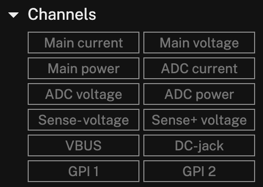
Within the channels available for measurement, the following can be found:
- Main current: include a graph of the current measured at the Otii hardware main connectors in the recordings
- Main power: include a graph of the power measured at the Otii hardware main connectors in the recordings
- Main voltage: include a graph of the voltage measured at the Otii hardware main connectors in the recordings
- ADC voltage: include a graph of the voltage measured at the ADC connectors in the recordings. This is measured on ADC+ pin. Single-ended from ADC+ to AGND; see an example of how to connect the ADC to measure voltage
- ADC current: include a graph of the current measured at the ADC connectors in the recordings. This is a differential measurement between ADC+ and ADC- pin; see an example of how to set the ADC resistor
- ADC power: include a graph of the power measured at the ADC connectors in the recordings
- SENSE +/- voltage: include a graph of the voltage measured at the SENSE+ and/or SENSE- pins in the expansion port. Single-ended measured compared to AGND
- VBUS: include a graph of the VBUS voltage
- DC-jack: include a graph of the DC-jack voltage
- GPI1 & GPI2: include a graph of the signal measured at the GPI1 and/or GPI2 pins in the expansion port. These pins are digital, and their value depends on how you have configured your digital voltage level in the supply mode
UART
UART (Universal Asynchronous Receiver/Transmitter) is a device-to-device communication protocol that allows interface and talk to exchange among devices. Within the Otii 3 Desktop App, the UART settings allow engineers and developers to:
- monitor and analyze data transmitted directly from the device under test (DUT) to the Otii 3 Desktop App
or transmit data directly from the Otii 3 Desktop App to the DUT; for example, send AT commands to the DUT while simultaneously observing the behavior and response via the console log.
By capturing and analyzing the UART data displayed within the Otii 3 console log, developers can gain insights into the DUT's behavior and precisely identify and troubleshoot any issues that might be causing the DUT's energy source-drain.
You can either use the built in UART of your Otii hardware, or you can use use a third party USB UART.
Enable the UART of your Otii hardware
1 While configuring the DUT in the CONTROL section of the Otii 3 Desktop App, navigate to the last setting option: Uart. 2 Set the baud rate on the respective field. To guarantee serial communication, assign the same baud rate as the one assigned in the DUT. 3 Enable the serial communication in the Channels option by clicking the UART log button. Upon enabling it, the console log will be automatically displayed at the bottom section of the Otii 3 Desktop App.
Once activated, with the additional connection required to establish serial communication between the DUT and the Otii hardware, the data transmitted will be displayed on the console log after the power supply is switched ON and the recording starts.
Enable an USB UART
If you have a third party USB UART connected to your computer it will be shown below the Otii hardware with the name of the computer device it is connected to. To add it, click the Add button.

Set the baudrate of the device and click in UART log to enable it for recording.

Firmware management
To ensure the proper operation of the Otii hardware with the latest version of the Otii 3 Desktop App, it is important to keep the hardware up to date with the latest firmware version available.
Once the Otii 3 Desktop App detects a new firmware version for the connected Otii hardware, a yellow exclamation mark icon shown in the CONTROL section indicates a new firmware is available. To upgrade it, you can:
- click on the exclamation mark icon, and choose Upgrade firmware,
- or, navigate to Devices > Upgrade firmware to latest.
Note that the upgrade firmware option is only available if the connected Otii hardware requires an upgrade. Otherwise, it will be visible but disabled.Once the firmware upgrade starts, the following behavior will be observed on the Otii hardware:
- Otii Ace Pro: the LED will start blinking red and blue quickly, then turn off for a few seconds, turn on yellow, and stay blue—the same state it was before the firmware upgrade. Then, it will automatically reconnect to the Otii 3 Desktop App
- Otii Arc Pro: It will restart, and when the upgrade is finished, it will automatically reconnect to the Otii 3 Desktop App
Upgrade firmware from file...
In case the Otii hardware needs to be upgraded to another firmware version, for testing and/or compatibility with particular features, it can be upgraded by:
- Navigate to Devices > Upgrade firmware from file.
- Choose the firmware file shared by the Qoitech team, and click open.
- Once opened, the firmware is upgraded in a few seconds, following the same behavior previously described on this page.
Calibration
To guarantee accurate measurements, the Otii hardware, both the Otii Arc Pro and the Otii Ace Pro can be calibrated when required. It is recommended to calibrate before any measurement requiring the best accuracy, especially ultra-low currents.
Calibrate a single connected Otii Arc Pro/Otii Ace Pro
- Open the Otii 3 Desktop App, and open/create a project.
- In the Otii 3 Desktop App toolbar, navigate to Device > Calibrate.
Once the calibration starts, the following behavior will be observed on the Otii hardware:
- Otii Ace Pro: the LED will start blinking white slowly, then turn off for a few seconds and turn on blue - the same state it was before the calibration.
- Otii Arc Pro: It will restart when the calibration is finished.
Calibrate all the Otii hardware connected
- Open the Otii 3 Desktop App, and open/create a project.
- In the Otii 3 Desktop App toolbar, navigate to Device > Calibrate all devices
Once calibration starts, the same behavior on the Otii hardware previously described on this page can be observed.