Jenkins integration
 These features require an Automation Toolbox license.
If you have a valid license for the automation toolbox you can enable a TCP server in Otii, making it possible to control Otii from another application. Using this feature you could e.g. use Otii in a continuous integration environment to automatically keep track of how firmware changes affects the energy consumption.
The following example shows how to add a test job that uses Otii in combination with Jenkins to make sure that a firmware change doesn't affect the energy consumption in a negative way.
Our test system
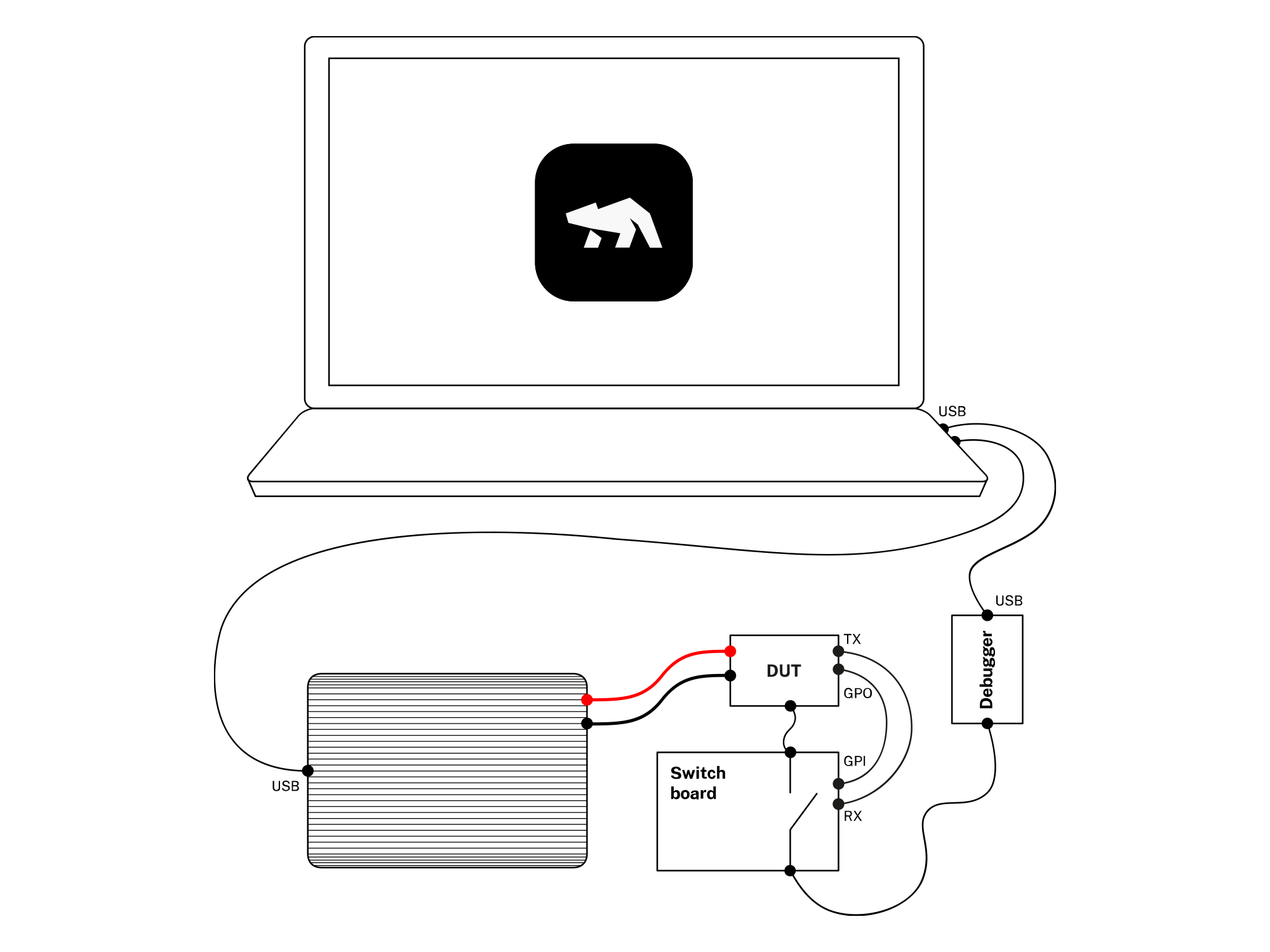
In this example we are using a ST32 Cortex M4 programmed with a ST-Link debugger. The board is powered by the Otii, and is connected to the ST-Link using the SWD interface to make it possible to flash the device with new firmware. To get a realistic measurement of the energy consumed, the ST-Link needs to be disconnected during the actual measurement.
For this reason we have developed a simple switch board that is connected to the expansion port of the Otii Arc, and is controlled by the GPO of the Arc. This makes it possible to connect the SWD when flashing the device, and then disconnect it when doing the energy measurements.
The device connects to the RX and the GPI1 of the Otii Arc. These are used in this example to mark the start and stop of parts of the measurements we want to verify.
The Python Otii Client
You need to install the Otii python client first, read more about it in the section Scripting with Python.
A first start
Create a test python script named otii_test.py. We will use the built in python unit test
framework unittest to run our tests. We will use xmlrunner to create JUnit test reports.
First you need to install the xmlrunner dependency:
python3 -m pip install unittest-xml-reportingCreate a file called otii_test.py and add the following code:
#!/usr/bin/env python3
import unittest

class OtiiTest(unittest.TestCase):
    def test_energy_consumption(self):
        pass

if __name__ == '__main__':
    import xmlrunner
    unittest.main(testRunner=xmlrunner.XMLTestRunner(output='test-reports'))
Running the test script
Run the script to see that it works:
python3 otii_test.py

Running tests...
----------------------------------------------------------------------
.
----------------------------------------------------------------------
Ran 1 test in 0.000s

OK
Configure the Otii TCP Server
See the TCP Server for information about how to configure and start the TCP server, either using the Otii desktop client, or using the Otii command line tool.
If you want to automatically start the server from your test script, read more in the section Python scripting.
Connecting to the Otii TCP Server
The next step is to connect to the Otii TCP server from the test script:
#!/usr/bin/env python3
import unittest
from otii_tcp_client import otii_client

class OtiiTest(unittest.TestCase):
    otii = None
    device = None

    @classmethod
    def setUpClass(cls):
        # Connect to Otii
        client = otii_client.OtiiClient()
        OtiiTest.otii = client.connect()

if __name__ == '__main__':
    import xmlrunner
    unittest.main(testRunner=xmlrunner.XMLTestRunner(output='test-reports'))
Configuring the Otii Arc
Now we query Otii for all the available devices, and try to find the correct Arc to use.
By giving each Arc a unique name, you will be sure that you are using the correct one.
...
TEST_DEVICE_NAME = 'Ace'

class AppException(Exception):
    '''Application Exception'''
...
class OtiiTest(unittest.TestCase):
    ...
    @classmethod
    def setUpClass(cls):
        ...
        devices = [
            device
            for device in OtiiTest.otii.get_devices()
            if device.name == TEST_DEVICE_NAME
        ]
        if len(devices) != 1:
            raise AppException(f'Cannot find one device named "{TEST_DEVICE_NAME}"')
        device = devices[0]
        OtiiTest.device = devices[0]

        device.set_main_voltage(4.0)
        device.set_exp_voltage(3.3)
        device.set_max_current(0.5)
        device.set_uart_baudrate(115200)
    ...
We configure the main out and the expansion port to 4.0 V, we set the max current to 500 mA and configure the UART to a baudrate of 115000.
Measurement
Now we are ready to start a measurement.
...
import time
...
MEASUREMENT_DURATION = 40
...
class OtiiTest(unittest.TestCase):
    ...
    def test_energy_consumption(self):
        otii = OtiiTest.otii
        device = OtiiTest.device

        project = otii.get_active_project()

        device.enable_channel('mc', True)
        device.enable_channel('rx', True)
        device.enable_channel('i1', True)

        project.start_recording()
        device.set_main(True)
        time.sleep(MEASUREMENT_DURATION)
        device.set_main(False)
        project.stop_recording()
    ...
Analyzing the result
The demo system using the UART to send out messages of the state of the firmware, and it is using the digital output to mark the start and stop of the active period.
Using RX to analyze data
In this system, the DUT sends the log message "Connecting..." at the start of an activity period. We use two of these messages to extract the energy consumed for a complete cycle.
...
START_OF_CYCLE_MESSAGE = 'Connecting...'
MIN_ENERGY = 2 # Joule
MAX_ENERGY = 4 # Joule
...
class OtiiTest(unittest.TestCase):
    ...
    def test_energy_consumption(self):
        ...
        recording = project.get_last_recording()
        index = 0
        count = recording.get_channel_data_count(device.id, 'rx')
        data = recording.get_channel_data(device.id, 'rx', index, count)
        values = data['values']
        timestamps = [value['timestamp'] for value in values if value['value'] == START_OF_CYCLE_MESSAGE]
        self.assertGreaterEqual(len(timestamps), 2, f'Need at least two "{START_OF_CYCLE_MESSAGE}" timestamps')

        statistics = recording.get_channel_statistics(device.id, 'mc', timestamps[0], timestamps[1])
        self.assertLess(statistics['energy'], MAX_ENERGY, 'One interval consumes to much energy')
    ...
Using GPI1 to analyze data
In this system, the DUT sends a small pulse when it wakes up to start a temperature measurement. We try to find the first two pulses, and extracts the energy consumed for this interval.
...
class OtiiTest(unittest.TestCase):
    ...
    def test_energy_consumption(self):
        ...
        recording = project.get_last_recording()
        index = 0
        count = recording.get_channel_data_count(device.id, 'i1')
        gpi1_data = recording.get_channel_data(device.id, 'i1', index, count)['values']
        timestamps = [gpi1_value['timestamp'] for gpi1_value in gpi1_data]
        self.assertGreaterEqual(len(timestamps), 4, 'Need at least four GPI1 pulses')

        statistics = recording.get_channel_statistics(device.id, 'mc', timestamps[0], timestamps[2])
        self.assertLess(statistics['energy'], MAX_ENERGY, 'One interval consumes to much energy')
        self.assertGreater(statistics['energy'], MIN_ENERGY, 'One interval consumes to little energy, is everything up and running?')
    ...
Building and uploading the firmware
This Jenkins job is going to be triggered when new firmware is merged to the main branch of the code repository. The first thing we need to do is to build the firmware, and then upload the new firmware to the device. We only need to do this once, so we add the class method setUpClass to the OtiiTest class, this will be called once before running the unit tests.
...
import subprocess
...
FIRMWARE_FLASH_CMD = 'cd firmware; make build; make flash'
...
class OtiiTest(unittest.TestCase):
    ...

    @classmethod
    def setUpClass(cls):
        ...

        # Update FW

        # Make sure the main output of the Otii is turned off.
        device.set_main(False)

        # The switch board is powered by the Otii +5V pin.
        device.enable_5v(True)

        # Enable the USB, and give the DUT time to startup.
        device.set_gpo(1, True)
        time.sleep(3.0)

        try:
            # Upload new firmware
            result = subprocess.call(FIRMWARE_FLASH_CMD, shell=True)
            if result != 0:
                raise AppException('Failed to upload new firmware')
            time.sleep(3.0)
        except Exception as error:
            raise error
        finally:
            # Disable the USB, and turn off the main power
            device.set_gpo(1, False)
            time.sleep(1.0)

        def test_energy_consumption(self):
        ...
You can get the complete Jenkins example from the Qoitech Github.